Portable electronic device and antenna structure thereof

An antenna structure and electronic device technology, applied to antennas, radiating element structure forms, and devices that enable antennas to work in different bands at the same time, can solve problems such as limited bandwidth, compressed antenna structure size, and inability to meet transmission requirements at the same time , to achieve the effect of short length, expanding low-frequency bandwidth, and meeting transmission requirements

Active Publication Date: 2014-05-07
WISTRON NEWEB
View PDF4 Cites 4 Cited by
  • Summary
  • Abstract
  • Description
  • Claims
  • Application Information

AI Technical Summary

Problems solved by technology

However, due to the thinning and thinning of wireless communication devices, the size of the antenna structure is also compressed, and the bandwidth is limited. Therefore, in the low-frequency part, the transmission requirements of the United States and Europe cannot be met at the same time.

Method used


Image

  • Portable electronic device and antenna structure thereof
  • Portable electronic device and antenna structure thereof
  • Portable electronic device and antenna structure thereof

Examples


Embodiment Construction

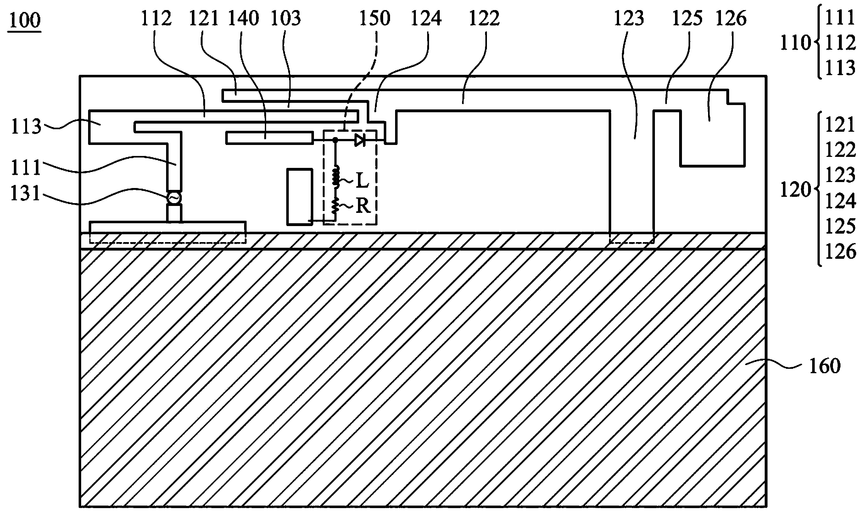
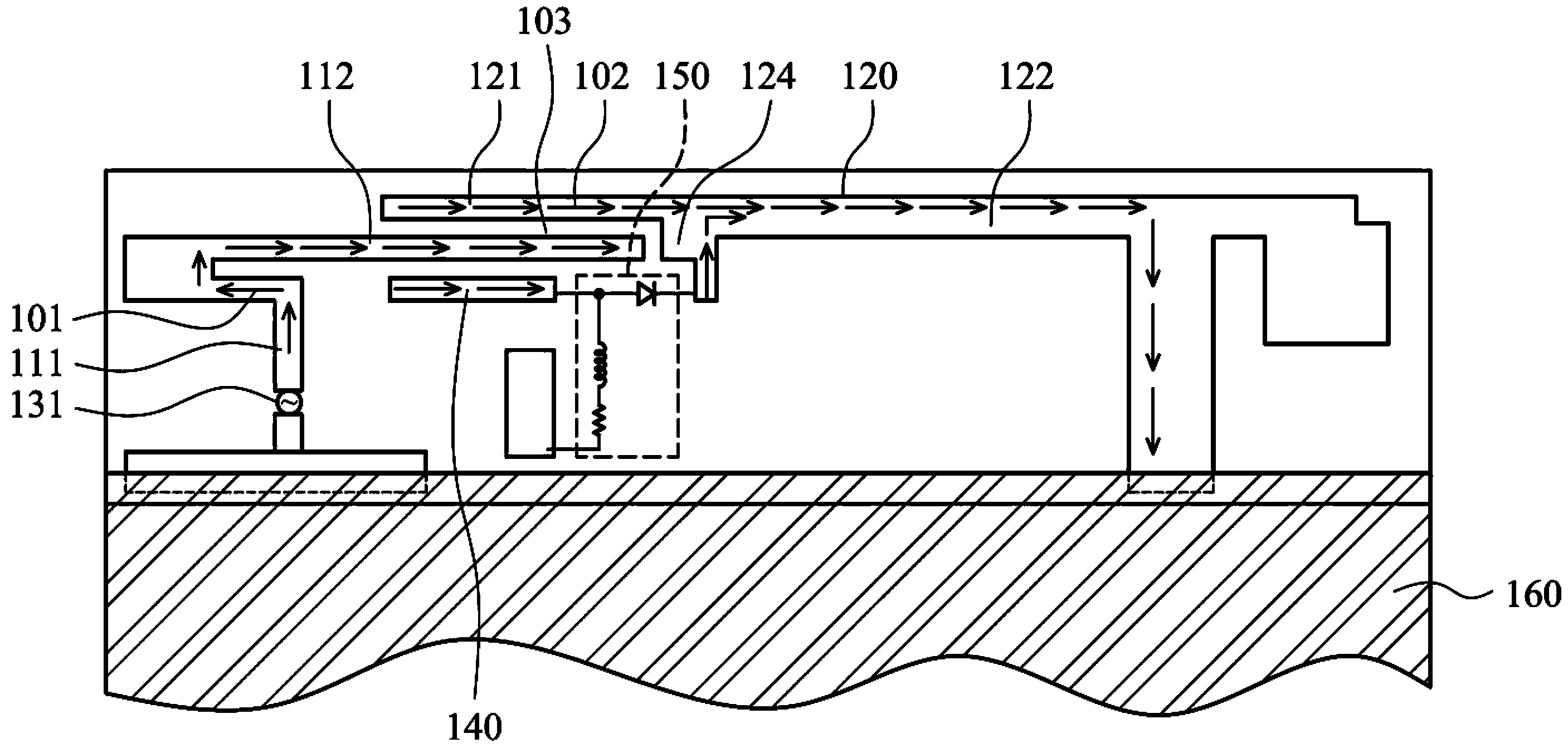
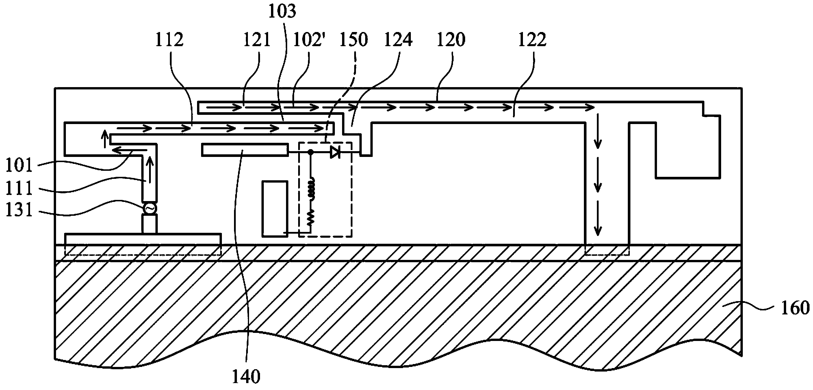
[0031] refer to figure 1 , which shows the antenna structure 100 according to the embodiment of the present invention, including a first radiator 110 , a second radiator 120 , a second coupling part 140 and a switching circuit 150 . The first radiator 110 includes a feeding portion 111 and a first radiator body 112 . A feeding source 131 is electrically connected to the feeding part 111 . The second radiator 120 includes a first coupling part 121, a second radiator body 122 and a ground part 123, the first coupling part 121 is connected to a first end 124 of the second radiator body 122, the ground The portion 123 is connected to the second radiator body 122 . The first radiator body 112 is at least partially located between the first coupling portion 121 and the second coupling portion 140 . The switching circuit 150 is connected to the second radiator 120 and the second coupling part 140 .

[0032] The first radiator body 112 is parallel to the first coupling portion 121...


PUM


Abstract

The invention discloses a portable electronic device and an antenna structure thereof. The antenna structure comprises a first radiator, a second radiator, a second coupling part and a switching circuit; the first radiator comprises a feed-in part and a first radiator body; the second radiator comprises a first coupling part, a second radiator body and a grounding part; the first coupling part is connected with a first end part of the second radiator body; the grounding part is connected with the second radiator body; and the first radiator body is partly located between the first coupling part and the second coupling part. When the antenna structure is in a first mode state, a pathway is formed between the second radiator body and the second coupling part by the switching circuit; and when the antenna structure is in a second mode state, an open way is formed between the second radiator body and the second coupling part by the switching circuit.

Description

technical field [0001] The present invention relates to an antenna structure, in particular to an antenna structure capable of changing operating frequency bands. Background technique [0002] At present, for a single wireless communication standard, there are still different operating frequency bands in different regions. Taking the LTE (Long Term Evolution) communication specification as an example, the operating frequency bands in the United States are 704~960MHz and 1710~2170MHz. The operating frequency bands in Europe are 791~960MHz and 1710~2170MHz. However, due to the thinning of wireless communication devices, the size of the antenna structure is also compressed, and the bandwidth is limited. Therefore, in the low frequency part, the transmission requirements of the United States and Europe cannot be met at the same time. Contents of the invention [0003] The present invention provides an antenna structure to solve the problems in the prior art, including a firs...

Claims


Application Information

Patent Timeline
Patent Type & Authority Applications(China)
IPC IPC(8): H01Q1/36H01Q5/00H01Q5/321
Inventor 陈俊宏邱义泓张家豪谢智森
Owner WISTRON NEWEB
Why Eureka
Try Eureka