Hydraulic self control flow converging pipe network flow cut-off control well

A technology of hydraulic self-control and confluence system, applied in the field of drainage pipe network system, can solve the problems of complicated structure of interception equipment, easy blockage of filter equipment, unadjustable drainage water level, etc. Effect

Active Publication Date: 2015-06-17
WUHAN SHENGYU DRAINING SYST
View PDF12 Cites 2 Cited by
  • Summary
  • Abstract
  • Description
  • Claims
  • Application Information

AI Technical Summary

Problems solved by technology

At present, the interception pipe network system is usually used to intercept the initial rainwater to the sewage pipe and send it to the sewage treatment plant for purification treatment. However, the pollution degree of the rainwater in the later period of the rainfall is relatively light. After pretreatment to intercept the suspended solids and solid particles in the water, Directly discharged into natural water bodies, but the current initial rain interception facilities have the following disadvantages: 1) The structure of the interception equipment is complex and the operation is difficult; 2) The filter equipment is easy to block during the pretreatment of the later rainwater before discharge; 3) The drainage water level Fixed and not adjustable

Method used


Image

  • Hydraulic self control flow converging pipe network flow cut-off control well
  • Hydraulic self control flow converging pipe network flow cut-off control well
  • Hydraulic self control flow converging pipe network flow cut-off control well

Examples


Embodiment Construction

[0033] The present invention will be further described in detail below in conjunction with the accompanying drawings to facilitate a clearer understanding of the present invention, but they do not limit the present invention.

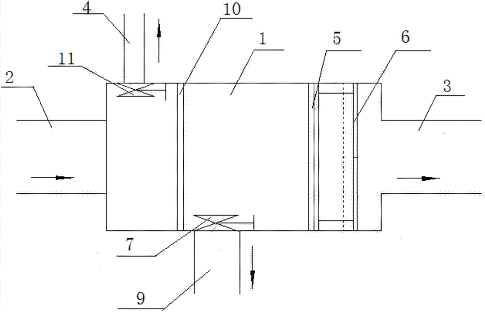
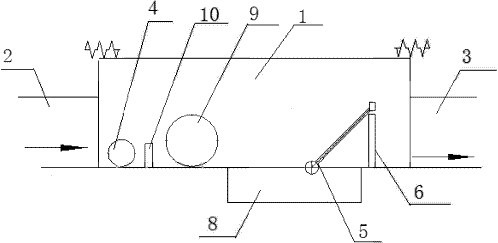
[0034] Such as figure 1 , figure 2 As shown, a hydraulic self-controlled confluence pipe network interception well includes a well body 1, the left end of the well body 1 is provided with a rainwater confluence inlet pipe 2, and the right end of the well body 1 is provided with a water outlet pipe 3, and the well body 1 is provided with a water outlet pipe 3. The first rain overflow weir 10 is arranged in sequence from left to right on the flow channel of 1, the height of the initial rain overflow weir 10 is the liquid level height corresponding to the interception multiple, the slag blocking buoy 5, and the multi-stage adjustable overflow plate 6, The bottom of the side wall of the well body 1 between the rain and sewage confluence inlet pipe 2 and t...


PUM


Abstract

The invention discloses a hydraulic self control flow converging pipe network flow cut-off control well, which comprises a well body, wherein a rain and sewage flow converging water inlet pipe is arranged at the left end of the well body, the right end of the well body is provided with a water outlet pipe, a primary rain overflow weir, a slag blocking floating tube and a multi-stage adjustable overflow plate are sequentially arranged on the flow passage of the well body from the left side to the right side, a sewage flow cut-off pipe is arranged at the bottom of the side wall of the well body between the rain and sewage flow converging water inlet pipe and the primary rain overflow weir, a floating tube flow cut-off check valve is arranged on the sewage flow cut-off pipe, a primary rain flow cut-off pipe is arranged at the bottom of the side wall of the well body arranged between the primary rain flow overflow weir and the multi-stage adjustable overflow plate, and a flow cut-off check valve is arranged on the primary rain flow cut-off pipe. The floating tube flow cut-off check valve is arranged at an inlet of the sewage flow cut-off pipe, in addition, the flow cut-off check valve is arranged at the inlet of the primary rain flow cut-off pipe so that the flow rate of the flow cut-off sewage and the primary rain can be controlled, and in addition, the reverse flow of the sewage and the primary rain can be prevented; the slag blocking floating tube is used for blocking slag, so the blocking phenomenon is avoided, the adjustable height of the discharge water level can be realized through the multi-stage adjustable overflow plate, further, the effective separation of the primary rain is realized, and the primary rain can be conveyed to sewage treatment plants to the maximum after the flow cut-off operation.

Description

technical field [0001] The invention relates to a drainage pipe network system, in particular to a hydraulic self-controlled combined pipe network interception well. Background technique [0002] The rain at the initial stage of rainfall is referred to as primary rain. In the early stage of rainfall, the rainwater dissolves a large amount of acid gas in the air, automobile exhaust, factory exhaust gas and other polluting gases. etc., causing the initial rain to contain a large amount of pollutants such as organic matter, pathogens, heavy metals, grease, and suspended solids. Therefore, the pollution degree of the initial rain is relatively high, usually exceeding that of ordinary urban sewage. If the early rainwater is directly discharged into natural The water body will cause very serious pollution to the water body, so the first rain needs to be treated. At present, the interception pipe network system is usually used to intercept the first rainwater to the sewage pipe an...

Claims


Application Information

Patent Timeline
Patent Type & Authority Patents(China)
IPC IPC(8): E03F5/10E03F5/14E03F7/02E03F9/00
Inventor 周超何锐
Owner WUHAN SHENGYU DRAINING SYST
Why Eureka
Try Eureka