Inter-RRU united channel correcting method and device

A technology of combined channel correction and equipment, applied in the field of communication

Active Publication Date: 2014-07-02
HUAWEI TECH CO LTD
View PDF8 Cites 10 Cited by
  • Summary
  • Abstract
  • Description
  • Claims
  • Application Information

AI Technical Summary

Problems solved by technology

[0004] The purpose of the embodiments of the present invention is to provide a joint channel correction method between R...

Method used


Image

  • Inter-RRU united channel correcting method and device
  • Inter-RRU united channel correcting method and device
  • Inter-RRU united channel correcting method and device

Examples


Embodiment 1

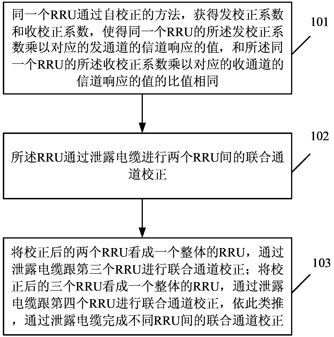
[0083] refer to figure 1 , figure 1 It is a flowchart of a method for inter-RRU joint channel correction provided in Embodiment 1 of the present invention. Such as figure 1 As shown, the method includes the following steps:

[0084] Step 101, the same Radio Remote Unit (RRU) obtains the transmission correction coefficient and the reception correction coefficient through a self-calibration method, so that the transmission correction coefficient of the same RRU is multiplied by the channel response of the corresponding transmission channel The value is the same as the ratio of the receiving correction coefficient of the same RRU multiplied by the channel response value of the corresponding receiving channel;

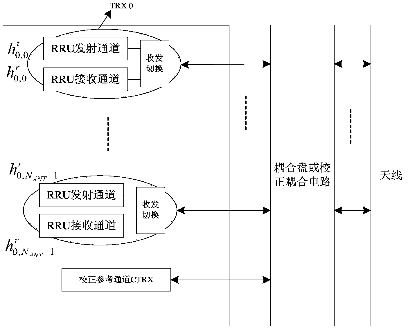
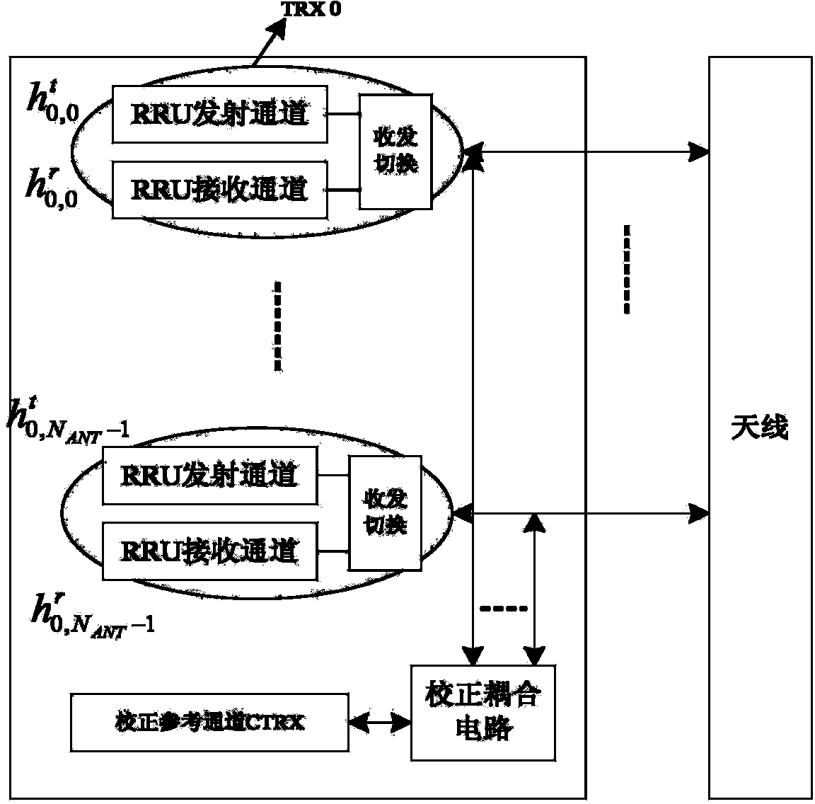
[0085] refer to figure 2 and image 3 , figure 2 is a simplified block diagram of a wireless access system provided in Embodiment 1 of the present invention, image 3 It is a schematic diagram of an external calibration RRU. The difference between an internal cali...

Embodiment 2

[0176] refer to Figure 6 , Figure 6 It is a flowchart of a method for joint channel correction between RRUs provided by Embodiment 2 of the present invention. Such as Figure 6 As shown, the method includes the following steps:

[0177] Step 601, selecting any one of the different RRUs as a reference RRU for joint channel correction;

[0178] Specifically, the calibration reference channel of a certain RRU is selected among multiple RRUs as a reference, and the calibration signals of all RRUs are transmitted or received from the calibration reference channel of the selected RRU, assuming that the calibration reference channel of RRU0 is selected as the reference calibration. reference channel reference Figure 4 As shown, different RRUs select RRU0 as a reference RRU for joint channel calibration, and all RRUs perform joint channel calibration through the RRU0.

[0179] In step 602, the different RRUs perform joint channel correction with the selected RRU through the le...

Embodiment 3

[0199] refer to Figure 7 , Figure 7 It is a schematic diagram of a method for inter-RRU joint channel correction of an internal and external correction type provided by Embodiment 3 of the present invention.

[0200] In order to complete the joint channel calibration between multiple internal calibration RRUs, replace the RF cable connected to the antenna of a service channel of the RRU with a leaky cable (denoted as the second calibration leaky cable), and perform joint channel calibration between RRUs; refer to Figure 8 , the calibration process between RRUs is as follows:

[0201] Step 1: Same as Step 101 in Embodiment 1, RRU0 and RRU1 respectively complete the calibration;

[0202] Receive correction factor It can be expressed as:

[0203] β k , i UL ( n ) = 1 h ...


PUM


Abstract

The embodiment of the invention provides an inter-RRU united channel correcting method and device. According to the method, external correction type or internal correction type inter-RRU united channel correction is conducted by means of a leaky cable, the ratios of the values obtained after the transmitting correction coefficients of transmission channels of different RRUs are multiplied by the corresponding channel responses of the transmission channels to the values obtained after the receiving correction coefficients of receiving channels of different RRUs are multiplied by the corresponding channel responses of the receiving channels are made identical, correction of channels among multiple cells is realized, and the requirement of JT for channel reciprocity are met.

Description

technical field [0001] The invention belongs to the communication field, and in particular relates to a method and equipment for inter-RRU joint channel correction. Background technique [0002] In the Time Division Duplexing (TDD) system, the base station estimates the uplink channel by detecting the Sounding Reference Signal (SRS) signal sent by the user (User Equipment, UE), and uses the TDD system to uplink and downlink Reciprocity, the estimated uplink channel is used as the downlink channel for beamforming. Although the uplink and downlink are reciprocal in theory in the TDD system, in the actual system, the uplink and downlink channels respectively introduce different radio frequency channels of the base station, and the responses of these radio frequency channels are different, which requires channel correction. These channels are compensated. Through theoretical analysis, it is found that the beamforming requirements can be met only if the ratios of the uplink / dow...

Claims


Application Information

Patent Timeline
IPC IPC(8): H04L25/03H04B7/06H04B5/00
Inventor 易雄书官鹭
Owner HUAWEI TECH CO LTD
Why Eureka
Try Eureka