A method and device for joint channel correction between RRUs
A technology of joint channel correction and equipment, applied in the field of communication
- Summary
- Abstract
- Description
- Claims
- Application Information
AI Technical Summary
Problems solved by technology
Method used
Image
Examples
Embodiment 1
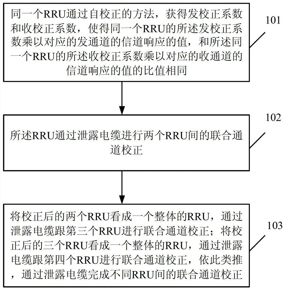
[0083] refer to figure 1 , figure 1 It is a flowchart of a method for inter-RRU joint channel correction provided in Embodiment 1 of the present invention. Such as figure 1 As shown, the method includes the following steps:
[0084] Step 101, the same Radio Remote Unit (RRU) obtains the transmission correction coefficient and the reception correction coefficient through a self-calibration method, so that the transmission correction coefficient of the same RRU is multiplied by the channel response of the corresponding transmission channel The value is the same as the ratio of the receiving correction coefficient of the same RRU multiplied by the channel response value of the corresponding receiving channel;
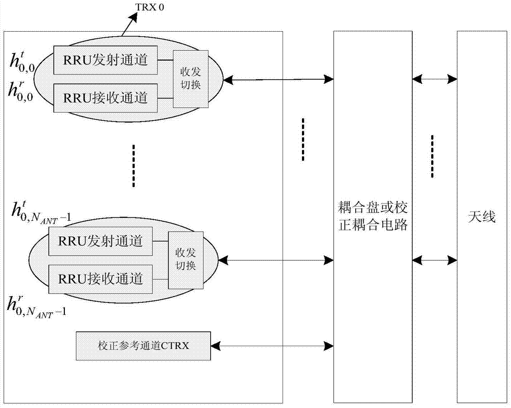
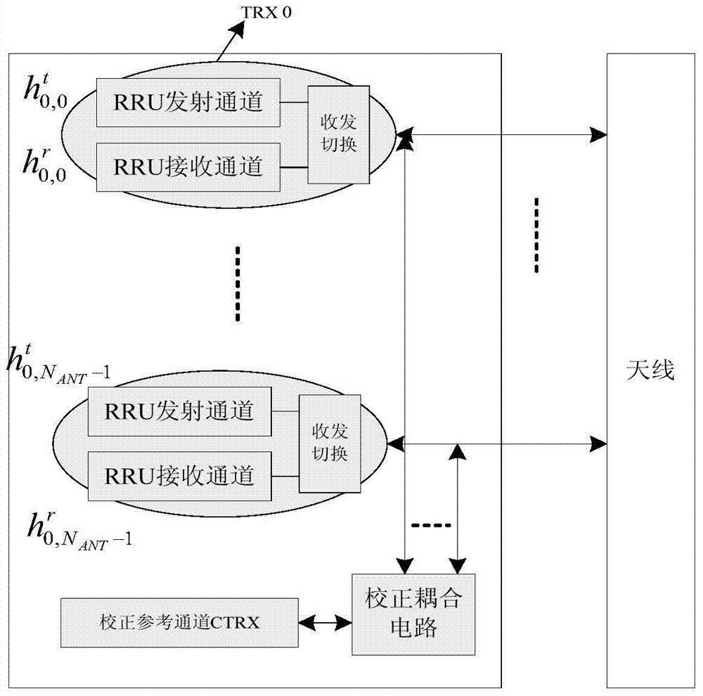
[0085] refer to figure 2 and image 3 , figure 2 is a simplified block diagram of a wireless access system provided in Embodiment 1 of the present invention, image 3 It is a schematic diagram of an external calibration RRU. The difference between an internal cali...
Embodiment 2
[0177] refer to Figure 6 , Figure 6 It is a flowchart of a method for joint channel correction between RRUs provided by Embodiment 2 of the present invention. Such as Figure 6 As shown, the method includes the following steps:
[0178] Step 601, selecting any one of the different RRUs as a reference RRU for joint channel correction;
[0179] Specifically, the calibration reference channel of a certain RRU is selected among multiple RRUs as a reference, and the calibration signals of all RRUs are transmitted or received from the calibration reference channel of the selected RRU, assuming that the calibration reference channel of RRU0 is selected as the reference calibration. reference channel reference Figure 4 As shown, different RRUs select RRU0 as a reference RRU for joint channel calibration, and all RRUs perform joint channel calibration through the RRU0.
[0180] In step 602, the different RRUs perform joint channel correction with the selected RRU through the le...
Embodiment 3
[0200] refer to Figure 7 , Figure 7 It is a schematic diagram of a method for inter-RRU joint channel correction of an internal and external correction type provided by Embodiment 3 of the present invention.
[0201] In order to complete the joint channel calibration between multiple internal calibration RRUs, replace the RF cable connected to the antenna of a service channel of the RRU with a leaky cable (denoted as the second calibration leaky cable), and perform joint channel calibration between RRUs; refer to Figure 8 , the calibration process between RRUs is as follows:
[0202] Step 1: Same as Step 101 in Embodiment 1, RRU0 and RRU1 respectively complete the calibration;
[0203] Receive correction factor It can be expressed as:
[0204] k=0,1
[0205] The hair correction coefficient can be expressed as:
[0206] k=0,1
[0207] Preferably, using relative correction (with reference to the correction coefficient of the first service channel), the coefficient...
PUM
 Abstract
Description
Claims
Application Information
 - R&D
- Intellectual Property
- Life Sciences
- Materials
- Tech Scout
- Unparalleled Data Quality
- Higher Quality Content
- 60% Fewer Hallucinations
Browse by: Latest US Patents, China's latest patents, Technical Efficacy Thesaurus, Application Domain, Technology Topic, Popular Technical Reports.
© 2025 PatSnap. All rights reserved.Legal|Privacy policy|Modern Slavery Act Transparency Statement|Sitemap|About US| Contact US: help@patsnap.com


