Pulse electronic fence contact alarm system and detection method

A pulse electronic and alarm system technology, applied in the electronic field, can solve the problems of inability to realize single-wire contact electronic fence alarm, bypass "no alarm, electronic fence no alarm, etc.

Inactive Publication Date: 2014-09-17
SHANGHAI GATO INFORMATION TECH
View PDF8 Cites 6 Cited by
  • Summary
  • Abstract
  • Description
  • Claims
  • Application Information

AI Technical Summary

Problems solved by technology

[0003] There are generally three technical problems in the existing high-voltage pulse electronic electronic fence system: image 3 As shown, the first technical problem is that "single-wire contact" does not alarm, that is, when a person touches a conductive cable on the electronic fence, the electronic fence does not alarm; the second technical problem is that "bypass" does not alarm, That is: in the physical fence project, when the length of the fence wire is changed, the protective ability of the fence is changed, so the electronic fence of the high-voltage pulse electronic method loses its blocking effect, which is the so-called "bypass problem"; when the wire 1. Cut off and connect with long wire 2. In this way, it is the "bypass problem" of the electronic fence
The third technical problem is that "jumping" does not alarm, that is, between two spaced conductive cables, use a wire to connect
[0004] Chinese invention patent ZL201110063434.2 discloses an induction intelligent electronic fence and its protection method (authorization announcement number: CN102163356A, authorization announcement date: August 24, 2011), the induction electronic fence is an induction and pulse mode (also High and low voltage pulse voltage), which cannot solve the technical problem of cross-connection and / or bypass without alarm
[0005] Chinese invention patent application ZL201110083254.0 discloses a pulsed electronic fence alarm system (application publication number: CN102737458A, application publication date: October 17, 2012), the pulsed electronic fence alarm system can only be detected when it is cut off or short-circuited Alarm, electronic fence alarm when single-line contact, crossover and bypass cannot be realized
[0006] Chinese invention patent ZL201010242776.6 discloses a high-voltage pulse electronic fence system (authorized announcement number: CN10196490B, authorized announcement date: December 19, 2012), and the high-voltage pulse electronic fence can only be detected in the case of short circuit and open circuit An alarm is issued, and the electronic fence alarm cannot be realized when single-line contact, crossover and bypass

Method used


Image

  • Pulse electronic fence contact alarm system and detection method
  • Pulse electronic fence contact alarm system and detection method
  • Pulse electronic fence contact alarm system and detection method

Examples


Embodiment 1

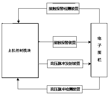
[0031] A new type of pulse electronic fence contact alarm system, such as figure 1 A new type of pulse electronic fence contact alarm system is shown, including a host control module, the host control module, contact alarm device, electronic fence and contact alarm detection device constitute the first loop; the host control module, high voltage The pulse emission device, electronic fence, and high-voltage pulse detection device constitute the second loop.

[0032] The host control module is used to control the contact alarm signal and the high-voltage pulse signal generated by the contact alarm device and the high-voltage pulse emission device, and transmit the contact alarm signal and the high-voltage pulse signal to the front end of the pulse electronic fence; at the same time, the slave pulse electronic fence The contact alarm signal and high-voltage pulse signal transmitted and detected by the contact alarm detection device and high-voltage pulse detection device are...

Embodiment 2

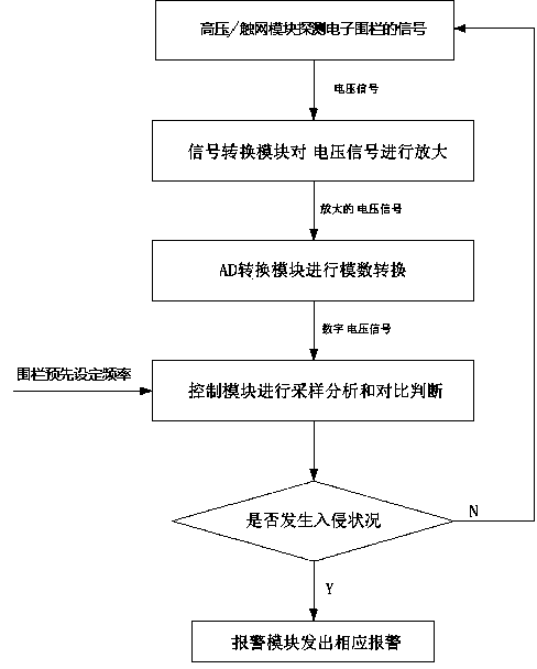
[0047] combined with figure 2 Further elaborate on the detection method of the pulse electronic fence contact net system of the present invention:

[0048] A novel pulse electronic fence contact alarm method comprises the following steps:

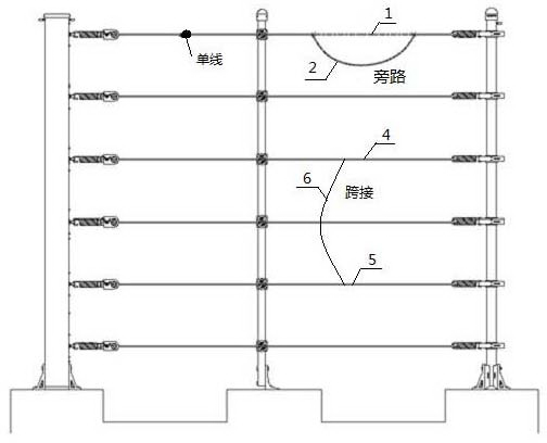
[0049] Step 1, under the control of the host control module, the contact alarm device generates an alarm signal, and the high-voltage pulse emission device generates a high-voltage pulse signal of the electronic fence, wherein the contact signal is one of single-wire contact, bypass, and jumper signals or several; then the contact alarm device and the high-voltage pulse emission device transmit the above-mentioned contact alarm signal and high-voltage pulse signal to the front end of the pulse electronic fence respectively; The incoming network contact alarm signal and high voltage pulse signal;

[0050] Step 2, amplifying the above-mentioned detected grid contact alarm signal and high-voltage pulse signal through the signal conversi...


PUM


Abstract

The invention relates to a pulse electronic fence contact alarm system and a detection method. The alarm system comprises a host control module, a contact alarm device, a contact alarm detection device, a high-voltage pulse emission device and a high-voltage pulse detection device. The host control module controls net contact alarm signals generated by the contact alarm device and high-voltage pulse signals generated by the high-voltage pulse emission device and the host control module analyzes and judges the net contact alarm signals and the high-voltage pulse signals, wherein the signals are transmitted through a pulse electronic fence and detected by the detection device. The method includes the steps that high-voltage signals and the net contact alarm signals of the electronic fence are detected so as to be acquired through the detection device; output high voltage signals and net contact voltage signals are amplified; the amplified high voltage signals and the amplified net contact voltage signals are converted into digital signals for analysis and judgment. According to the system and method, the net contact alarm signals and the high-voltage pulse signals are combined, so that the technical problems of alarm failure of single line contact, bridging and the bypass in a pulse electronic fence system are solved.

Description

technical field [0001] The invention belongs to the field of electronic technology, in particular to a pulse electronic fence contact alarm system and a detection method. Background technique [0002] In ordinary residential areas, villa residential areas, enterprises and institutions, factories, warehouses, substations, power plants, schools, detention centers, prisons, airports, military bases, government agencies, key cultural relics protection units and other places, perimeter security and perimeter security are required. Boundary intrusion alarm facilities. With the increasing demand for safety protection, the safety protection system of various new detection technologies has developed rapidly, and the perimeter protection products have become more and more abundant. For civilian perimeter alarm and prevention systems, the dual identification technology of infrared detection technology and infrared microwave technology is generally used, but the alarm system using thes...

Claims


Application Information

Patent Timeline
Patent Type & Authority Applications(China)
IPC IPC(8): G08B13/12H05C1/06
Inventor 王雷
Owner SHANGHAI GATO INFORMATION TECH
Why Eureka
Try Eureka