A continuous punching device for u-shaped pipe

A punching device and U-shaped tube technology, which is applied in the field of continuous punching devices for U-shaped pipes, can solve the problems of low punching efficiency, inability to realize continuous punching, complex structure, etc., and achieve the effect of improving punching efficiency

Active Publication Date: 2016-08-24
冠达星股份有限公司
View PDF7 Cites 0 Cited by
  • Summary
  • Abstract
  • Description
  • Claims
  • Application Information

AI Technical Summary

Problems solved by technology

[0002] Holes are processed on the pipe wall of the pipe, usually by drilling or milling on the machine tool, and also by punching. For example, the Chinese patent with publication number CN101708520B discloses a pipe punching device , but its structure is complicated, and continuous punching cannot be realized, and the punching efficiency is low

Method used


Image

  • A continuous punching device for u-shaped pipe
  • A continuous punching device for u-shaped pipe

Examples


Embodiment Construction

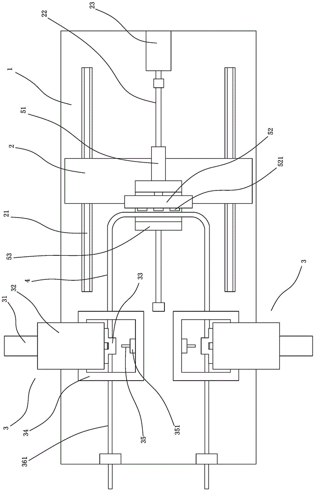
[0019] refer to figure 1 , figure 2 As shown, a U-shaped pipe continuous punching device includes a base 1, two punching mechanisms 3 symmetrically arranged on the base at the front and rear, a sliding seat 2 arranged on the base 1 that can move horizontally and horizontally, and a driving slide The lateral movement mechanism for the lateral movement of the seat 2, the clamping mechanism arranged on the sliding seat 2 for clamping the U-shaped pipe 4 in the middle, the control device connected with the stamping mechanism 3, the clamping mechanism and the lateral movement mechanism respectively, and the control device Used to control the coordination of various agencies.

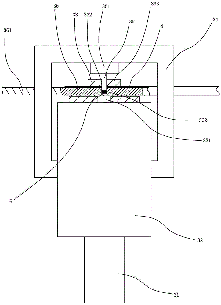
[0020] The punching mechanism includes a fixed frame 32, a movable frame 34, a mold base 33, a mandrel 36, an oil cylinder 31 and a punch 35. The fixed frame 32 is arranged on the base 1, and the movable frame 34 can be arranged on the base relative to the fixed frame 32 to move back and forth. 1; both the...


PUM


Abstract

A continuous punching device for U-shaped pipes, comprising a base, two punching mechanisms symmetrically arranged on the base at the front and rear, a sliding seat arranged on the base that can move horizontally and horizontally, and a lateral movement mechanism that drives the sliding seat to move laterally , the clamping mechanism arranged on the sliding seat for clamping the U-shaped pipe in the middle, the control device connected with the punching mechanism and the lateral movement mechanism respectively, the punching mechanism includes a fixed frame, a movable frame, a mold base, and a mandrel , driving parts and punches, the present invention has the advantages of simple structure, convenient operation and high punching efficiency.

Description

technical field [0001] The invention relates to a continuous punching device for U-shaped pipes, which is used for continuous punching on straight pipe sections of U-shaped pipes. Background technique [0002] Holes are processed on the pipe wall of the pipe, usually by drilling or milling on the machine tool, and also by punching. For example, the Chinese patent with publication number CN101708520B discloses a pipe punching device , but its structure is complicated, and continuous punching cannot be realized, and the punching efficiency is low. Contents of the invention [0003] The object of the present invention is to provide a continuous punching device for linear pipes with simple structure, convenient operation and high punching efficiency, aiming at the deficiencies of the prior art. [0004] The purpose of the present invention is achieved through the following technical solutions: [0005] A continuous punching device for U-shaped pipes, characterized in that it...

Claims


Application Information

Patent Timeline
Patent Type & Authority Patents(China)
IPC IPC(8): B21D28/28B21D28/34B21D43/13B21D45/02
Inventor 杨建明
Owner 冠达星股份有限公司
Why Eureka
Try Eureka