Punching equipment for processing control equipment

A technology for controlling equipment and punching, applied in metal processing, wood punching and other directions, can solve the problems of inconvenient operation for staff, poor processing efficiency, inability to control multiple groups of equipment components for punching processing, etc., to achieve convenient adjustment processing, improvement The effect of overall machining efficiency

Inactive Publication Date: 2022-03-01
徐州安荣机械制造有限公司
View PDF0 Cites 0 Cited by
  • Summary
  • Abstract
  • Description
  • Claims
  • Application Information

AI Technical Summary

Problems solved by technology

[0002] Punching refers to punching various graphics on steel plates, leather, cloth, wood, etc. Punching equipment is used for auxiliary use, but the current punching equipment cannot realize subsequent processing feed adjustment after the control equipment components are fixed, and cannot cooperate with the punching unit for continuous interval punching
[0003] The prior art has the following deficiencies: the overall processing efficiency of the existing punching equipment is not good, continuous punching cannot be performed on multiple groups of control equipment components, and the current punching equipment cannot realize subsequent processing after the control equipment components are fixed The feed adjustment cannot cooperate with the punching unit for continuous interval punching, which is not convenient for the staff to operate. At the same time, the current punching equipment cannot realize the fine-tuning of the punching spacing of the control equipment components.

Method used


Image

  • Punching equipment for processing control equipment
  • Punching equipment for processing control equipment
  • Punching equipment for processing control equipment

Examples


Embodiment Construction

[0022] The following will clearly and completely describe the technical solutions in the embodiments of the present invention with reference to the drawings in the embodiments of the present invention.

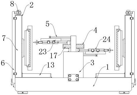
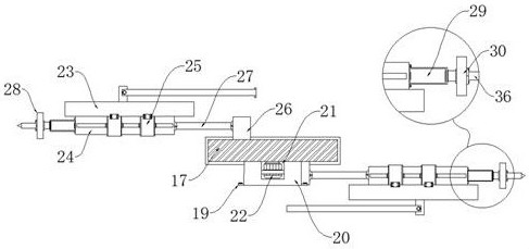
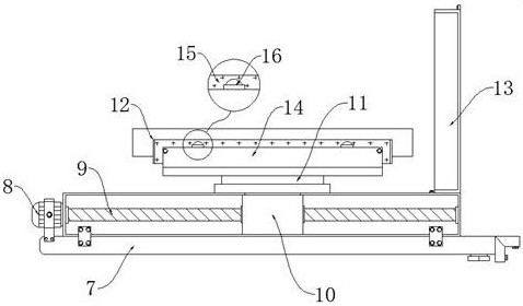
[0023] Such as Figure 1-5 As shown, the present invention provides a technical solution: a punching equipment for processing control equipment, including a workbench 1, two sets of lifting assemblies 2, a center table 3, a transmission assembly 4 and two sets of punching assemblies 5, the lifting assemblies 2 Symmetrically locked and installed on both sides of the upper surface of the workbench 1, the center platform 3 is locked and installed at the center of the upper surface of the workbench 1, the transmission component 4 is installed on the top of the center platform 3, and the punching component 5 is symmetrically installed On both sides of the center platform 3 and connected with the upper surface and the lower surface of the transmission assembly 4 , and the output end...


PUM


Abstract

The punching equipment for control equipment machining comprises a workbench, two lifting assemblies, a center table, a transmission assembly and two punching assemblies, the lifting assemblies are symmetrically installed on the two sides of the upper surface of the workbench in a locked mode, the center table is installed at the center of the upper surface of the workbench in a locked mode, and the transmission assembly is installed at the top of the center table. The punching assemblies are symmetrically installed on the two sides of the center table and connected with the upper surface and the lower surface of the transmission assembly, and the output ends of the punching assemblies face the lifting assembly. The two sets of control equipment elements are symmetrically installed on the two sides of the workbench, the transmission assembly is installed in the center of the two sets of control equipment elements, the transmission assembly serves as a power source, the punching assembly is driven to conduct corresponding circulating reciprocating extension to achieve punching treatment on the control equipment elements on the two sides, the overall punching efficiency is improved, and meanwhile under cooperation of the lifting assembly, the punching efficiency is improved. In the punching process, control equipment elements are driven to move and feed, continuous punching is achieved, and operation and use of workers are facilitated.

Description

technical field [0001] The invention relates to the related technical field of punching equipment, in particular to a punching equipment for processing control equipment. Background technique [0002] Punching refers to punching various graphics on steel plates, leather, cloth, wood and other materials to meet different needs. In the production of control equipment, the shell needs to be punched to ensure a good heat dissipation effect of the control equipment. Therefore, it is necessary to cooperate with Punching equipment is used for auxiliary use, but the current punching equipment cannot realize subsequent processing feed adjustment after the control equipment components are fixed, and cannot cooperate with the punching unit for continuous interval punching. [0003] The existing technology has the following disadvantages: the overall processing efficiency of the existing punching equipment is not good, and continuous punching can not be performed on multiple groups of c...

Claims


Application Information

Patent Timeline
Patent Type & Authority Applications(China)
IPC IPC(8): B21D28/26B26F1/02B27M1/04
CPCB21D28/26B26F1/02B27M1/04
Inventor 孙青柏
Owner 徐州安荣机械制造有限公司
Why Eureka
Try Eureka