Device and method for adjusting roller type punching distance

A technology of adjusting roller and punching, which is applied in the field of plastic processing, can solve the problems of offset of punching position and inaccurate control of plate transfer position, so as to reduce the cost of mold manufacturing, increase product diversification, and realize the effect of automatic production.

Active Publication Date: 2018-03-30
NORTH CHINA UNIVERSITY OF SCIENCE AND TECHNOLOGY
View PDF16 Cites 0 Cited by
  • Summary
  • Abstract
  • Description
  • Claims
  • Application Information

AI Technical Summary

Problems solved by technology

However, this kind of punching device is not precise in controlling the transmission position of the plate when the speed is adjusted, which easily leads to the deviation of the punching position

Method used


Image

  • Device and method for adjusting roller type punching distance
  • Device and method for adjusting roller type punching distance
  • Device and method for adjusting roller type punching distance

Examples


Embodiment Construction

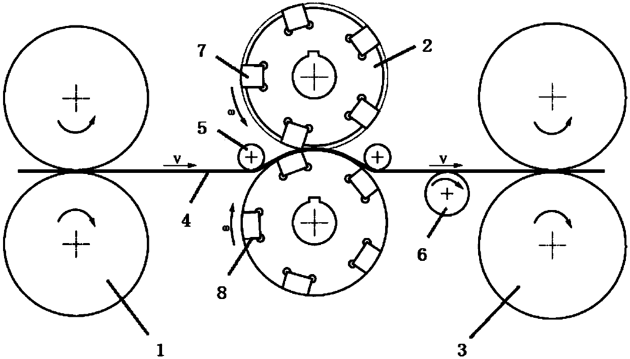
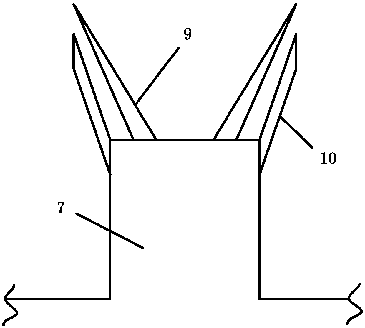
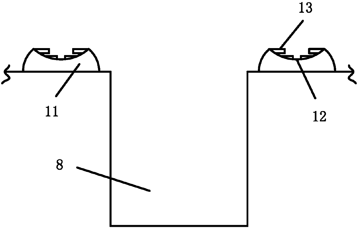
[0027] refer to Figure 1-5 A specific embodiment of the present invention includes two guide rollers 1 that are crimped up and down, two punching rollers 2 that are crimped up and down, two correction rollers 3 that are crimped up and down, and the sheet material 4 passes through the guide rollers in turn. Material pressure roller 1, punching pressure roller 2 and correction pressure roller 3, pressure roller 5 is arranged on both sides of punching pressure roller 2, and speed measuring roller 6 is arranged between punching pressure roller 2 and correction pressure roller 3; The surface of the punching roller 2 positioned above is evenly provided with a punch 7, the surface of the punching roller 2 positioned below is provided with a die 8 corresponding to the punch 7 one by one, and the top of the punch 7 is provided with a cutting strip 9, which is cut The outer edge of the strip 9 is fixed with a rubber outer edge 10, the cutting strip 9 and the rubber outer edge 10 are sl...


PUM


Abstract

The invention discloses a device for adjusting the roller type punching distance. The device comprises two guide press rollers in up-and-down compression joint, two punching press rollers in up-and-down compression joint and two correction press rollers in up-and-down compression joint. A plate sequentially penetrates the guide press rollers, the punching press rollers and the correction press rollers. Pressing rollers are arranged on the two sides of the punching press rollers correspondingly. A speed measurement roller is arranged between the punching press rollers and the correction press rollers. Convex molds are evenly arranged on the surface of the punching press roller located on the upper portion. Concave molds in one-to-one correspondence to the convex molds are arranged on the surface of the punching press roller located on the lower portion. Cutting strips are arranged at the tops of the convex molds. Rubber outer edges are fixed to the outer sides of the cutting strips. Thecutting strips and the rubber outer edges are attached to the inner side walls of the concave molds in a sliding manner. Rubber flanges are arranged at the tops of the concave molds. A groove is formed in the top of each rubber flange. Multiple annular rubber pieces are arranged on the inner wall of each groove. According to the device, the defects in the prior art can be overcome, and the punching position accuracy is improved.

Description

technical field [0001] The invention relates to the technical field of plastic processing, in particular to a device and a method for adjusting the pitch of roller punching holes. Background technique [0002] The roll punching process is to install multiple pairs of punches and dies on the rolls, and the rolls are synchronized and rotated in opposite directions to achieve the purpose of high-speed continuous punching. It has the advantages of high production efficiency, low punching force, low noise, small footprint and small investment. It is suitable for metal coils with a thickness of less than 3.0mm, and can realize punching, blanking, edge trimming and incision. It shows broad application prospects in the fields of construction, storage, packaging and automobiles. [0003] Checking the existing literature, it can be known that the strip relies on the friction between it and the roll to move forward, so the strip advance speed is the same as the roll rotation speed. T...

Claims


Application Information

Patent Timeline
Patent Type & Authority Applications(China)
IPC IPC(8): B21D28/26B21D43/02B21D43/09B21C51/00
CPCB21C51/00B21D28/26B21D43/021B21D43/09Y02E60/10
Inventor 刘倩李佳凝郑小平张荣华田亚强陈连生
Owner NORTH CHINA UNIVERSITY OF SCIENCE AND TECHNOLOGY
Why Eureka
Try Eureka