Brick cutter for construction site and method for cutting bricks through brick cutter

A construction site and brick cutting machine technology, which is applied in the field of brick cutting machines for construction sites, can solve the problems of poor section shape and difficulty in cutting bricks, etc., and achieve the effects of good section quality, convenient cutting, and convenient operation

Inactive Publication Date: 2019-03-05
南京舜力建设工程有限公司
View PDF0 Cites 0 Cited by
  • Summary
  • Abstract
  • Description
  • Claims
  • Application Information

AI Technical Summary

Problems solved by technology

[0003] The purpose of the present invention is to provide a brick cutting machine for construction sites, which solves the technical defects in the prior art that the construction site is difficult to cut bricks and the section shape of the bricks is poor after separation

Method used


Image

  • Brick cutter for construction site and method for cutting bricks through brick cutter
  • Brick cutter for construction site and method for cutting bricks through brick cutter
  • Brick cutter for construction site and method for cutting bricks through brick cutter

Examples


Embodiment 1

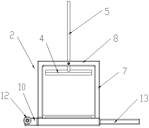
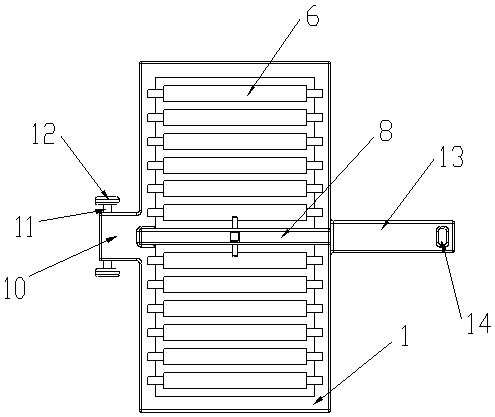
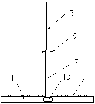
[0029] Such as Figure 1-Figure 4 The shown brick cutting machine for a construction site includes a base 1 for placing bricks, a support frame 2 arranged on the base 1, a lower cutter 3 and an upper cutter 4, and the lower cutter 3 is detachably installed on the base 1 and the edge of the lower cutter 3 is upward, the specific detachable installation method is to open an installation groove (not shown in the figure) on the base 1, and place the lower cutter 3 in the installation groove. For example, it is preferable to place fillers such as pieces of paper in the installation groove to make the installation of the lower cutter 3 and the base 1 more firm. The top of the support frame 2 is provided with a cutter mounting frame 5, and the blade mounting frame 5 5 and the supporting frame 2 form a vertical moving pair, so that the tool mounting frame 5 can move up and down on the title frame 2, so that the upper tool 4 can move in the vertical direction, and the upward movement o...

Embodiment 2

[0036] The technical solution of the present embodiment adopts the method for cutting bricks with the brick cutting machine described in the first embodiment, and the method of the present embodiment specifically includes the following seven steps:

[0037] Step 1, place the brick cutter for the ground on the level ground.

[0038] Step 2, insert the positioning pin 9 into the second through hole and the fixing hole, fix the tool mounting frame 5 and the horizontal support frame 8, and keep the distance between the lower tool 3 and the upper tool 4 greater than the thickness of the brick.

[0039] Step 3, place one end of the brick to be cut on the conveying roller 6 from the side of the brick cutter.

[0040] Step 4, forcefully push the bricks to the other side of the brick cutter until the part where the bricks need to be cut is located directly under the upper knife 4 .

[0041] Step 5, pull out the positioning pin 9 from the second through hole and the fixing hole.

[00...


PUM


Abstract

The invention discloses a brick cutter for a construction site and a method for cutting bricks through the brick cutter. The brick cutter comprises a base (1) used for containing the bricks, a supporting framework (2) arranged on the base (1), a lower tool (3) and an upper tool (4); the lower tool (3) is detachably installed on the base (1), and an edge of the lower tool (3) is upward; a tool mounting frame (5) is arranged on the top of the supporting framework (2) and forms a vertical movable pair with the supporting framework (2); the upper tool (4) is installed at the bottom of the tool mounting frame (5), and an edge of the upper tool (4) is downward; and the upper tool (4) and the lower tool (3) are parallel and located in the same vertical plane. The brick cutter has the beneficial effects that the brick cutter can conveniently cut the bricks, the quality of fracture surfaces of the cut bricks is good, and meanwhile, the brick cutter has the advantages of being simple in structure and convenient to operate.

Description

technical field [0001] The invention relates to a brick cutting machine for a construction site and a method for cutting bricks. Background technique [0002] On the construction site, especially on the construction site of the wall, it is often necessary to divide the brick into two parts because the remaining distance after laying bricks within one end distance is small, and it is difficult to place a whole brick. The way to divide the bricks is to cut the bricks directly with a tile knife. The construction workers need to swing the tile knife to cut the bricks at the position they think is suitable according to their experience. Take the tile knife, at the moment when the tile knife collides with the brick, the vibration of the brick and the tile knife is very large, which will cause damage to the hands of the construction worker, and it is difficult to cut the brick. On the other hand, using the tile knife It is difficult to control the cross-sectional shape of the bric...

Claims


Application Information

Patent Timeline
Patent Type & Authority Applications(China)
IPC IPC(8): B28D1/22
CPCB28D1/223
Inventor 诸德明诸靖
Owner 南京舜力建设工程有限公司
Why Eureka
Try Eureka