Circuits and methods for adjustable peak inductor current and hysteresis for burst mode in switching regulators

a switching regulator and peak inductor technology, which is applied in the direction of electric variable regulation, process and machine control, instruments, etc., can solve the problems of reducing unable to maximize the efficiency of switching regulators, and inherent current limitation capabilities, so as to achieve large output voltage ripple and reduce efficiency

Inactive Publication Date: 2008-02-07
ANALOG DEVICES INT UNLTD
View PDF37 Cites 99 Cited by
  • Summary
  • Abstract
  • Description
  • Claims
  • Application Information

AI Technical Summary

Benefits of technology

[0023]It is therefore an object of the present invention to provide circuits and methods for permitting a user to vary the burst threshold level, thereby allowing for the selection of a desired minimum peak inductor current level in switching regulators operating in Burst Mode.
[0025]It is further an object of the present invention to provide circuits and methods for permitting the voltage ripple of the regulated output voltage of a regulator to be more fully adjustable over a continuous range of values, so that the voltage ripple may be more finely tailored to suit the requirements of various applications.
[0030]The above preferred embodiments alleviate the problems associated with using a fixed minimum peak inductor current level and burst hysteresis. Accordingly, the present invention allows the output voltage ripple and efficiency of a switching regulator to be more fully adjustable to fit different application requirements. Furthermore, the present invention allows for large output voltage ripple without a loss of efficiency because an increase in hysteresis does not produce a corresponding increase in the magnitude of the current.

Problems solved by technology

They provide good line and load transient signal rejection, and possess inherent current-limiting capabilities during fault conditions (e.g., output short circuits).
Synchronous switching regulators differ from non-synchronous switching regulators in that a diode is replaced with a synchronous switching element, and the result, typically, is decreased power loss in the switching regulator.
The efficiency of switching regulators, however, is not always maximized and varies proportionally to the size of the load.
The above-described loss of efficiency at lighter loads is common in switching regulators that operate in a forced continuous mode of operation.
Therefore, these regulators may become inefficient for smaller loads because of the energy, in the form of gate charge, that is required to constantly turn the main switch and synchronous switch ON and OFF regardless of load conditions.
A disadvantage of some Burst Mode type regulators results from the inability to externally control the burst threshold level, which sets the minimum peak inductor current level.
For higher burst threshold levels, the efficiency at light loads is higher at the expense of higher output voltage ripple (an undesirable characteristic).
For lower burst threshold levels, the output voltage ripple is lower at the expense of slightly reduced efficiency for light loads.
Accordingly, because the burst threshold level, which sets the minimum peak inductor current level, is fixed internally in current regulators that operate in Burst Mode, the output voltage ripple and efficiency of the regulator cannot be tailored to fit the requirements of different applications.
At higher burst threshold levels, the efficiency at light loads would be higher at the expense of higher output voltage ripple (which, depending on the application, is an undesirable characteristic).
At lower burst threshold levels, the output voltage ripple would be lower at the expense of slightly reduced efficiency for light loads.
When the output voltage ripple exceeds a certain magnitude, however, there is a loss of efficiency in such regulators because of DC losses in the conduction path.

Method used


Image

  • Circuits and methods for adjustable peak inductor current and hysteresis for burst mode in switching regulators
  • Circuits and methods for adjustable peak inductor current and hysteresis for burst mode in switching regulators
  • Circuits and methods for adjustable peak inductor current and hysteresis for burst mode in switching regulators

Examples


Embodiment Construction

[0041]Many electronic products use DC-DC switching regulators to convert an input voltage into a regulated output voltage that may be higher or lower than the input voltage. Switching regulators use one or more active switching devices, an inductor or transformer, and a capacitor to store and transfer the energy into the load.

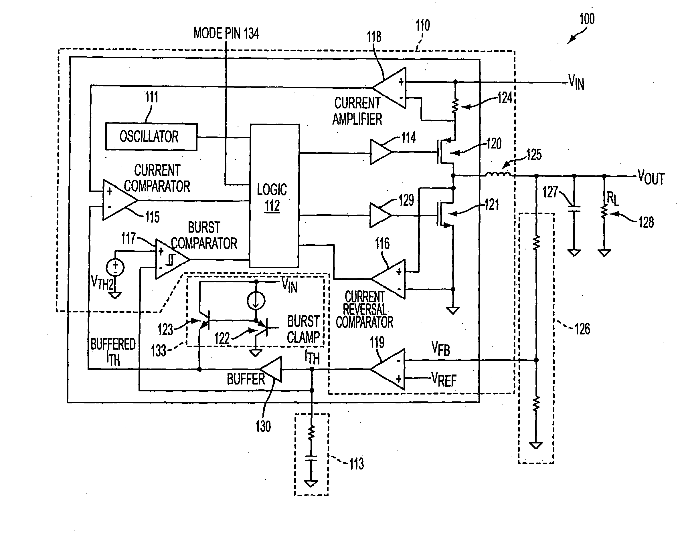
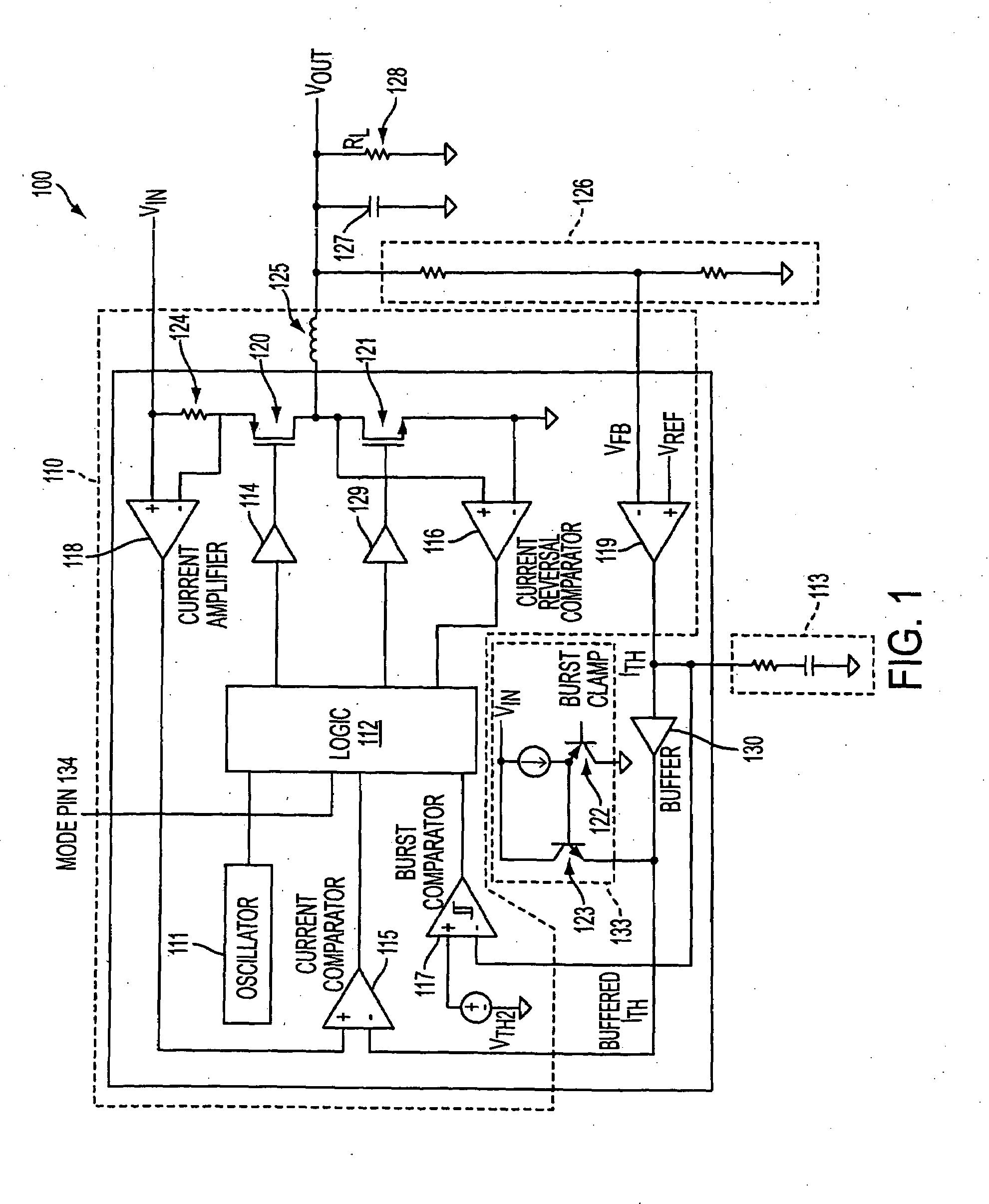
[0042]FIG. 1 shows a conventional, step-down switching voltage regulator using a constant-frequency, current-mode control architecture. The circuit operates as follows.

[0043]Voltage regulator 100 of FIG. 1 comprises control circuitry 110, which incorporates oscillator 111 or any other suitable device which is capable of providing the circuit with switch timing (i.e., by generating a narrow pulse at a constant frequency). At the beginning of each cycle this oscillator pulse propagates through logic 112, which then directs main switch driver 114 to turn main switch 120 ON. Logic 112 may comprise a pulse-width modulator (PWM) circuit or any other suitable circuit ...


PUM


Abstract

Switching regulator circuits and methods are provided for regulating output voltage that include an adjustable minimum peak inductor current level and adjustable burst comparator hysteresis for Burst Mode operation in switching regulators. Control over minimum peak inductor current level and burst comparator hysteresis is achieved during Burst Mode operation by allowing external user control of the burst threshold level and the burst comparator hysteresis. A single user-accessible input pin, two user-accessible input pins, or three user-accessible input pins may be used to distinguish between forced continuous and Burst Mode operations, set a burst threshold level, and set a burst comparator hysteresis during Burst Mode operation. The present invention may be applied to buck, boost, buck-boost, or any other suitable regulator circuit configuration. The present invention also may be employed with synchronous and non-synchronous switching regulators.

Description

FIELD OF THE INVENTION[0001]The present invention relates to circuits and methods for providing a user the ability to adjust the minimum peak inductor current level and hysteresis of switching regulators when operating in BURST MODE® (hereinafter, “Burst Mode”).BACKGROUND OF THE INVENTION[0002]The present invention relates to voltage regulators. More particularly, this invention relates to circuits and methods that provide the ability to adjust the minimum peak inductor current level and hysteresis for Burst Mode in current-mode DC-DC regulators (i.e. regulators that respond to measurements of output current or of signals indicative of output current).[0003]Voltage regulators are power supply circuits that use a closed loop design to provide a predetermined and substantially constant output voltage, even while using an input voltage source which may be poorly specified or fluctuating. Furthermore, many electronic products use voltage regulators to convert an input voltage into a reg...

Claims


Application Information

Patent Timeline
Patent Type & Authority Applications(United States)
IPC IPC(8): G05F1/00
CPCH02M3/156Y02B70/16H02M2001/0032Y02B70/10H02M1/0032G05F1/10
Inventor LEONARD, JASONESTEVES, JOEY MARTIN
Owner ANALOG DEVICES INT UNLTD
Why Eureka
Try Eureka