It has been found that cutter chipping, spalling and delaminating are common failure
modes for ultra hard flat top surface cutters.
It has been found by applicants that many cutters develop
cracking, spalling, chipping and partial fracturing of the ultra hard material cutting layer at a region of cutting layer subjected to the highest loading during drilling.
Cracks of sufficient length may cause the separation of a sufficiently large piece of ultra hard material, rendering the cutter 18 ineffective or resulting in the failure of the cutter 18.
When this happens, drilling operations may have to be ceased to allow for
recovery of the drag bit and replacement of the ineffective or failed cutter.
It has been found by applicants that cutters with sharp cutting edges or small back rake angles provide a good drilling ROP, but are often subject to
instability and are susceptible to chipping,
cracking or partial fracturing when subjected to high forces normal to the working surface.
Cutters with large back rake angles are often subjected to heavy wear, abrasion and shear forces resulting in chipping, spalling, and delaminating due to excessive downward force or
weight on bit (WOB) required to obtain reasonable ROP.
Thick ultra hard
layers that might be good for abrasion wear are often susceptible to
cracking, spalling, and delaminating as a result of residual thermal stresses associated with forming thick ultra hard
layers on the substrate.
However, selecting the best bit is not always straightforward because many formations have mixed characteristics (i.e., the
geological formation may include both hard and soft zones), depending on the location and depth of the well bore.
Where a
drill bit is operated outside the desired ranges of operation, the bit can be damaged or the life of the bit can be severely reduced.
For example, a
drill bit normally operated in one general type of formation may penetrate into a different formation too rapidly or
too slowly subjecting it to too little load or too much load.
For another example, a drill bit rotating and penetrating at a desired speed may encounter an unexpectedly hard material, possibly subjecting the bit to a “surprise” or sudden
impact force.
A material that is softer than expected may result in a
high rate of rotation, a high ROP, or both, that can cause the cutters to shear too deeply or to gouge into the
geological formation.
This can place greater loading, excessive shear forces and added heat on the working surface of the cutters.
Rotation speeds that are too high without sufficient WOB, for a particular drill bit design in a given formation, can also result in detrimental
instability (bit whirling) and chattering because the drill bit cuts too deeply or intermittently bites into the geological formation.
Cutter chipping, spalling, and delaminating, in these and other situations, are common failure
modes for ultra hard flat top surface cutters.
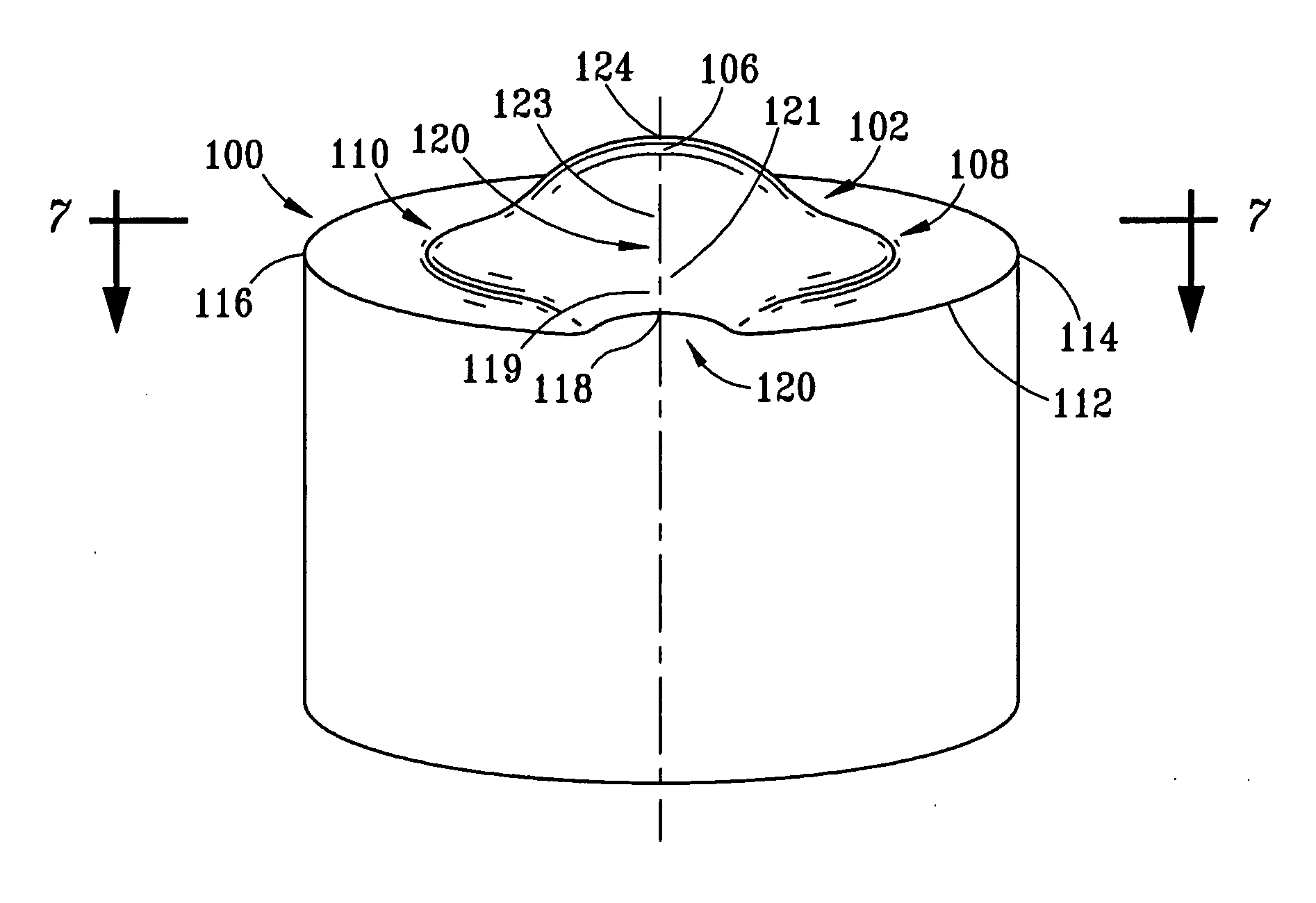
It has been found by applicants that while an axially symmetrical shape can provide some additional strength and support to the contact edge at some cutting depth, the cutting efficiency of these cutters may be reduced.
This can result in a corresponding increase in cracking, crack propagation, chipping and spalling.

