Funnel to counter out-splashing of a fluid being poured through it

a funnel and fluid technology, applied in the field of conventional funnels, can solve the problems of affecting the use of conventional funnels, and requiring slowdown that is not possible or practical, and is difficult to dispose of maintain conventional funnels upright during us

Inactive Publication Date: 2012-12-06
NIRMEL CHITTARANJAN N
View PDF7 Cites 12 Cited by
  • Summary
  • Abstract
  • Description
  • Claims
  • Application Information

AI Technical Summary

Benefits of technology

[0016]The principal object of this invention is to provide a f...

Problems solved by technology

All such “fluids” are known to suffer “splash-out” during their flow through conventional funnels.
This is where the initial problem is encountered: some of the arriving flow will often tend to continue going forward and right over the top of rim directly in front of it.
However, the requisite slowdown may not be possible or practical; and the problem is best addressed by improvements to the funnel structure.
Circumstances sometimes make it difficult to dispose and maintain a conventional funnel upright during use.
For example, in an emergency one might have to pour gasoline or diesel fuel, from a spare fuel can that lacks its own nozzle, into an automobile fuel tank through an intake that does not have a horizontal opening and so will not allow the conventional funnel to be used upright.
This can easily lead to some fuel splashing out over the lower edge of the bowl of the necessarily tipped funnel; especially when a person is operating alone and perhaps under awkward circumstances, e.g., in a poorly lit area or in inclement weather.
However, because of their relatively long bodies, they are not convenient for use outside garages or auto repair shops where the funnels can be set aside between uses so that residual fluid that drips from them can be routinely collected after each use.
These oppositely directed flows can cause incoming air bubbles to interrupt fluid outflow and make it irregular and pulsatile in nature, especially if the contributing container has thin flexible walls.
Such a fluid flow typically is gurgling, uneven, and at times randomly directed out of the contributing container.
Such an impact-induced flow reversal, and its inertial effects, can cause some of the bounced fluid to splash upward over the funnel rim a...

Method used


Image

  • Funnel to counter out-splashing of a fluid being poured through it
  • Funnel to counter out-splashing of a fluid being poured through it
  • Funnel to counter out-splashing of a fluid being poured through it

Examples


Embodiment Construction

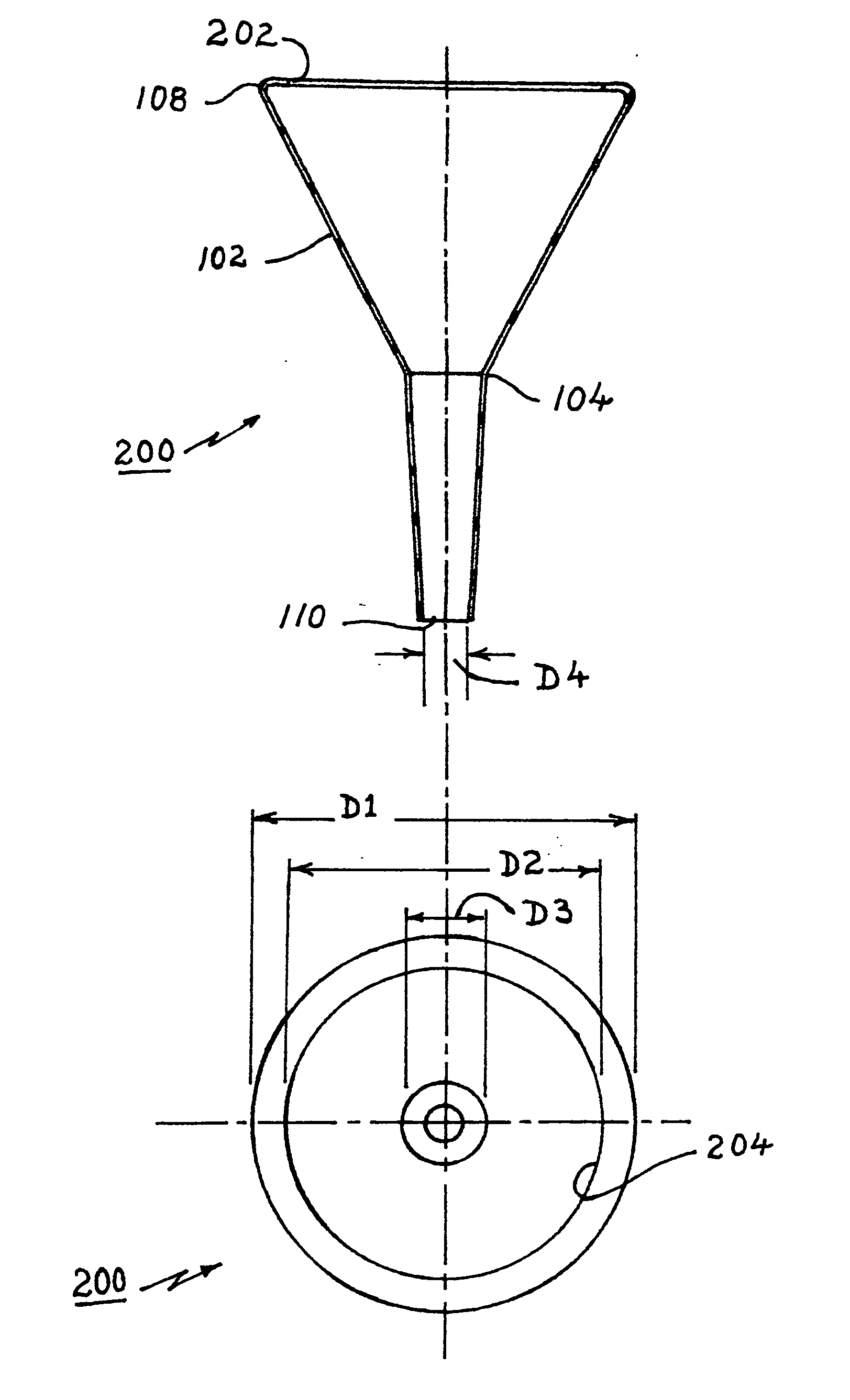
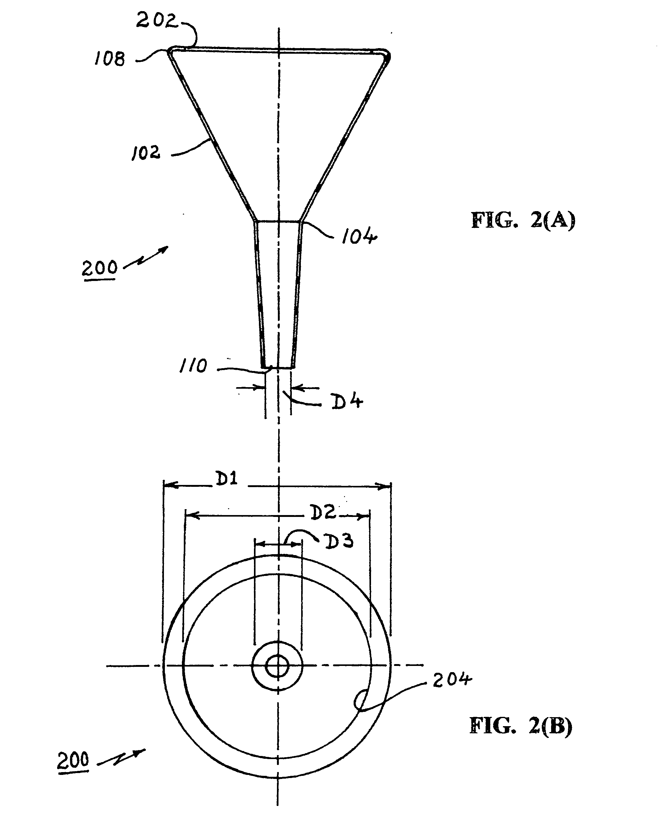
[0048]The improvements presented and claimed below are intended to be selectively applicable, individually or in combination with each other, to funnels of a variety of shapes and sizes, to counter splash-out from them of a variety of fluids—over a wide range of fluid viscosities.

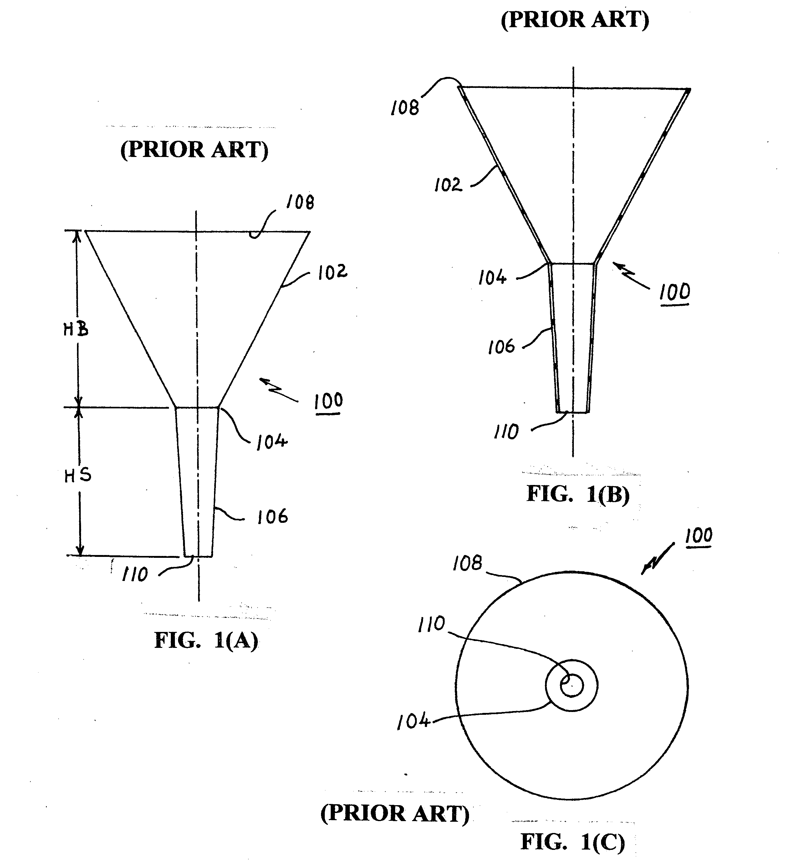
[0049]FIGS. 1(A), 1(B) and 1(C) show elevation, vertical cross-section, and top plan views, respectively, of a known portable funnel of a kind used for the transfer of fluids like milk, syrup, paint, motor oil, anti-freeze, transmission fluid, and the like. Such funnels, while not expensive, are not normally considered disposable and are often cleaned after each use and stored for future use. Non-disposable metal funnels, of the same general shape but generally somewhat larger, also are often used for similar but more substantial fluid transfers. Glass funnels of the same basic shape are often used in laboratories that handle highly reactive acids and / or other poisonous fluids.

[0050]Funnel 100 per FIGS. 1(A...


PUM

PropertyMeasurementUnit
Distanceaaaaaaaaaa
Flow rateaaaaaaaaaa
Flexibilityaaaaaaaaaa

Abstract

A conventional funnel that has a rimmed open bowl atop a spout, to guide a fluid flow poured in from a fluid-contributing source or container into a fluid-receiving container, is improved by the provision of a curved-in lip around the bowl rim. The curved-in lip intercepts any fluid seeking to splash out of the funnel for a variety of reasons, and redirects it back into the bowl to counter undesirable splash-out. The curved-in rim, even when of very small span, is effective in countering splash-out of true liquids, mixtures of non-sticking solid particulates in a liquid, dry flowing particulates and even small sized objects like peanuts. The provision of a perforated collar at the junction of the bowl and the spout, a flexible portion provided to the spout adjacent the same junction, and a plurality of outwardly extending vanes provided outside the spout, and flutes formed in the bowl to promote Coriolis-acceleration-influenced flow, added individually or in selected combinations, variously improve the funnel further by making it more securely locatable with respect to the receiving container, facilitating venting of displaced air therefrom, and promoting fluid throughflow via the funnel.

Description

FIELD OF THE INVENTION[0001]This invention relates to improvements to a conventional funnel, of the kind commonly used to help guide a fluid flow from a fluid-contributing container into a fluid-receiving container, to counter out-splashing from the funnel as the fluid is being poured through it. More particularly, it relates to simple structural improvements to a conventional funnel that significantly reduce the natural tendency of a fluid being poured through it to splash away from the intended transfer flow and out of the funnel due to factors such as: (a) the funnel not being held upright during the pour; (b) unevenly oriented or pulsating flow out of the contributing container, (c) inertial forces that tend to bounce back fast-pouring fluid from the inner surface of the funnel and over the funnel rim, (d) upward blowback of air and / or vapor from the receiving container, or (e) inadvertently caused instability of the funnel body during the pouring operation.BACKGROUND OF THE REL...

Claims


Application Information

Patent Timeline
IPC IPC(8): B65B39/00
CPCB67C11/02B67C2011/30
Inventor NIRMEL, CHITTARANJAN N.
Owner NIRMEL CHITTARANJAN N
Why Eureka
Try Eureka