Support bandage for a joint between bones

a support bandage and joint technology, applied in the field of support bands, can solve the problems of wearer discomfort, physical irritation of the wearer, and large wrinkles on the interior side of the support bandag

Inactive Publication Date: 2005-04-05
CHIANG PANG CHING
View PDF9 Cites 16 Cited by
  • Summary
  • Abstract
  • Description
  • Claims
  • Application Information

AI Technical Summary

Benefits of technology

The main objective of the invention is to provide a support bandage for a joint between bones which has a smooth curve and few wrinkles whereby the wearer's joint is supported in a comfortable manner.

Problems solved by technology

With reference to FIG. 6, when a joint with the support bandage (300) is bent, there are a lot of wrinkles formed at the interior side of the support bandage, and the wearer will feel discomfort.
Furthermore, the curve of the support bandage (400) caused by the sewn notches (43) is not smooth, and there are still some wrinkles formed at the interior side which can cause physical irritation to the wearer.

Method used


Image

  • Support bandage for a joint between bones
  • Support bandage for a joint between bones
  • Support bandage for a joint between bones

Examples


Embodiment Construction

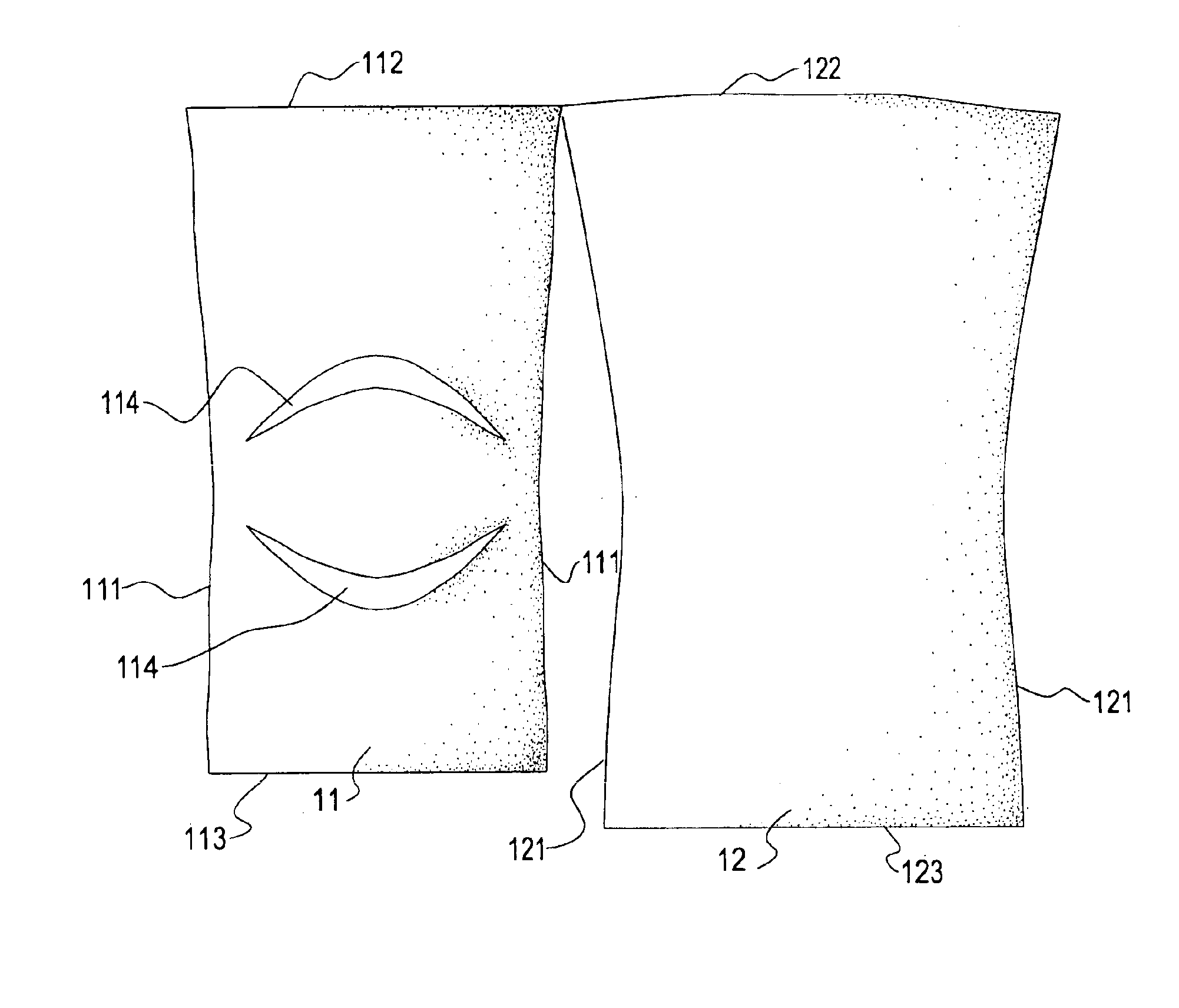
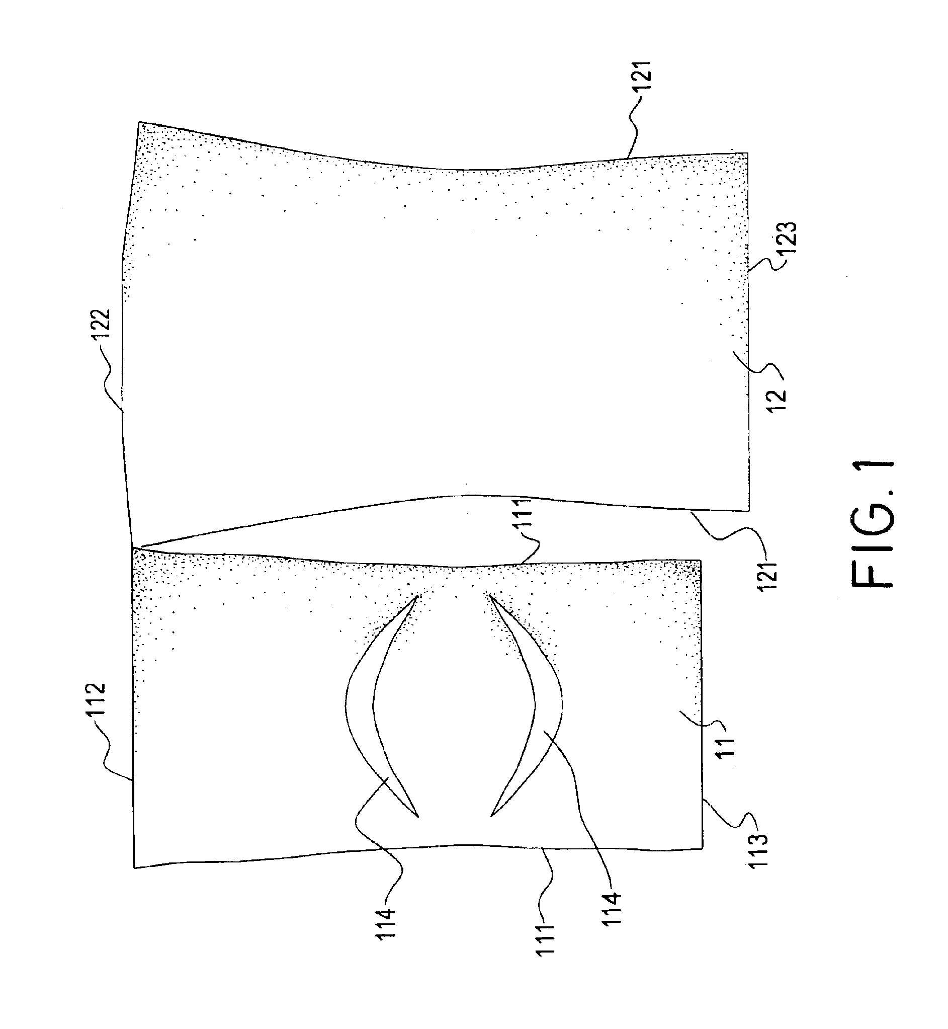
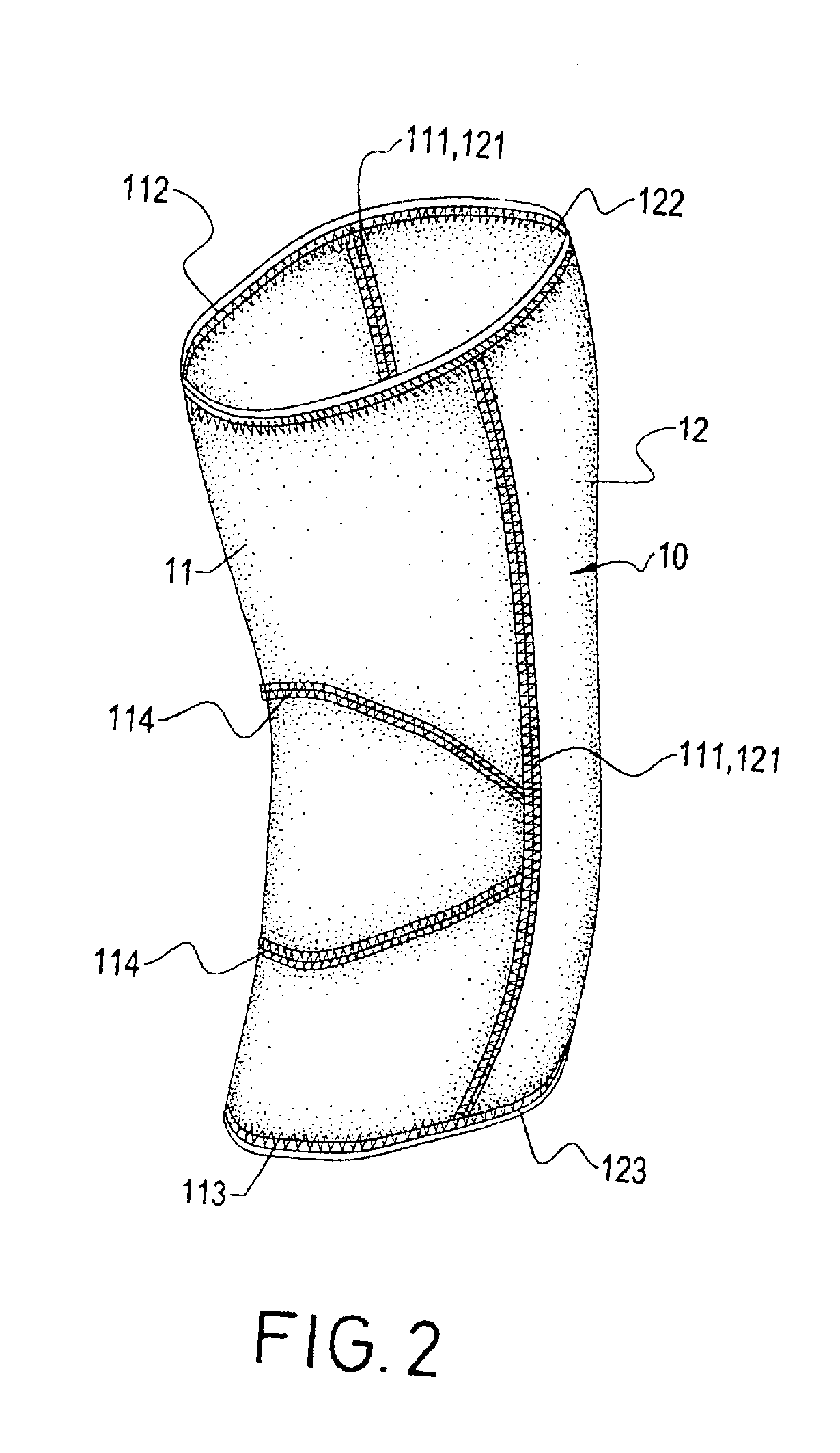
With reference to FIG. 1, an elastic cloth to form a support bandage for a joint between bones (10) in accordance with the invention is cut into a small fraction (11) and a large fraction (12) partially connected together.

The small fraction (11) has two opposite first longitudinal sides (111), a first top side (112) and a first bottom side (113); and the large fraction (12) has two opposite second longitudinal sides (121), a second top side (122) and a second bottom side (123). The two fractions (11, 12) are connected at two top corners thereof, and the first longitudinal sides (111) are shorter than the second longitudinal sides (121).

The second longitudinal sides (121) are incurved, and the second top side (122) is slightly longer than the second bottom side (123). The first longitudinal sides (111) are also incurved. Two crescent openings (114) are defined through the small fraction (11), wherein the upper opening (114) is curved upwards and the lower opening (114) is curved down...


PUM


Abstract

A support bandage for a joint between bones includes a small fraction having two opposite first longitudinal sides sewn with two opposite second longitudinal sides of a large fraction. The small fraction is incurved towards the large fraction, and has two arcuate seams on the small fraction. The segment between the two arcuate seams is more incurved than two end segments outside the arcuate seams, and the two arcuate seams are away from a wearer 's joint. Whereby, the support bandage can be tightly abut a knee or an elbow yet have few wrinkles and will not uncomfortably press the wearer.

Description

BACKGROUND OF THE INVENTION1. Field of the InventionThe present invention relates a support bandage to protect a wearer's joint such as knee or elbow.2. Description of Related ArtIn sports, players often wear elastic bandage to protect their joints such as knees and elbows. With reference to FIG. 4, a first conventional support bandage for a joint between bones is formed by a rectangular cloth (30) with two opposite longitudinal sides (31, 32). The longitudinal sides (31, 32) are sewn up to form a tubular support bandage (300) (as shown in FIGS. 5a and b). With reference to FIG. 6, when a joint with the support bandage (300) is bent, there are a lot of wrinkles formed at the interior side of the support bandage, and the wearer will feel discomfort.With reference to FIGS. 7 and 8, another improved support bandage for a joint between bones (400) is formed with a rectangular cloth (40) with two triangular notches (43) defined at two opposite longitudinal sides (41, 42). The triangular ...

Claims


Application Information

Patent Timeline
Patent Type & Authority Patents(United States)
IPC IPC(8): A61F13/06
CPCA61F13/061Y10S602/901
Inventor CHIANG, PANG-CHING
Owner CHIANG PANG CHING
Why Eureka
Try Eureka