Wire harness exterior protecting tube and wire harness

a protection tube and wire harness technology, applied in the direction of insulated conductors, cables, connection contact material, etc., can solve the problems of affecting the workability of the assembly, and the weight of the wire harness, so as to prevent the vertical flexing of the protection tube, facilitate the installation, and enhance the effect of assembly workability

Inactive Publication Date: 2012-07-24
AUTONETWORKS TECH LTD +2
View PDF10 Cites 14 Cited by
  • Summary
  • Abstract
  • Description
  • Claims
  • Application Information

AI Technical Summary

Benefits of technology

[0034]As described above, according to the present invention, in the sheathing protection tube for the wire harness to be cross-wired with both sides thereof in its longitudinal direction being supported by the door and the car body, by setting the one side section of the sheathing protection tube extended in the vertical direction thereof as the flat part, it is possible to prevent the sheathing protection tube from vertically flexing and effectively restrain the wire harness sheathed with the sheathing protection tube from hanging owing to the weight thereof.
[0035]As described above, the sheathing protection tube is formed by molding the elastic material having flexibility. In the portion of the other section, opposed to the flat part, which is sectionally rectangular gutter-shaped or sectionally semicircular ring-shaped and continuous with the one side section consisting of the flat part, there is formed the corrugated bellows part having the convex portions and the concave portions continuous and alternating with each other and longitudinally spaced at certain intervals. Thus although the vertically extended one side section of the sheathing protection tube is set as the flat part, the bellows part opposed to the flat part is capable of smoothly curving the sheathing protection tube in its longitudinal direction (horizontal direction).
[0036]As described above, the flat part is composed of the inner flat portion and the outer flat portion separately formed and layered one on the other; the upper end of any one of the inner flat portion and the outer flat portion is continuous with the upper side of the other section; and the lower end of the other of the inner flat portion and the outer flat portion is continuous with the lower side of the other section so that the flat part can be opened and closed over the entire length thereof in the longitudinal direction thereof. Therefore in inserting the wire harness into the sheathing protection tube, by opening the inner flat portion and the outer flat portion sideways, the wire harness can be easily inserted thereinto from the side surface of the tube. Thus this construction is capable of enhancing assembling workability. After the wire harness is inserted into the sheathing protection tube, the side surface of the sheathing protection tube can be closed by overlapping the outer flat portion on the inner flat portion. Thus the wire harness can be securely protected without being exposed to the outside.
[0037]As described above, by positioning the bellows part of the sheathing protection tube at the vertical portion disposed at the inner side of the car body when the slide door is fully closed and positioning the flat part of the sheathing protection tube at the vertical portion disposed at the outer side of the car body when the slide door is fully closed, it is possible to effectively prevent the cross-wired wire harness from hanging and allows the wire harness to follow the movement of the slide door with the wire harness being smoothly curved by the bellows part having a high elasticity.
[0038]As described above, by setting the bending restriction rib having a large thickness and a required length on the bellows part or / and the flat part of the sheathing protection tube where the bending angle is required to be restricted, it is possible to properly control the bending angle of the wire harness and prevent the wire harness and the peripheral members from interfering with each other with the wire harness smoothly following the movement of the slide door.

Problems solved by technology

But the wire harness cross-wired in a vehicle with the wire harness being sheathed with the flexible corrugate tube 1 has a problem that the wire harness hangs owing to its weight and interferes with peripheral members.
Thus the wire harness is liable to be damaged.

Method used


Image

  • Wire harness exterior protecting tube and wire harness
  • Wire harness exterior protecting tube and wire harness
  • Wire harness exterior protecting tube and wire harness

Examples


first embodiment

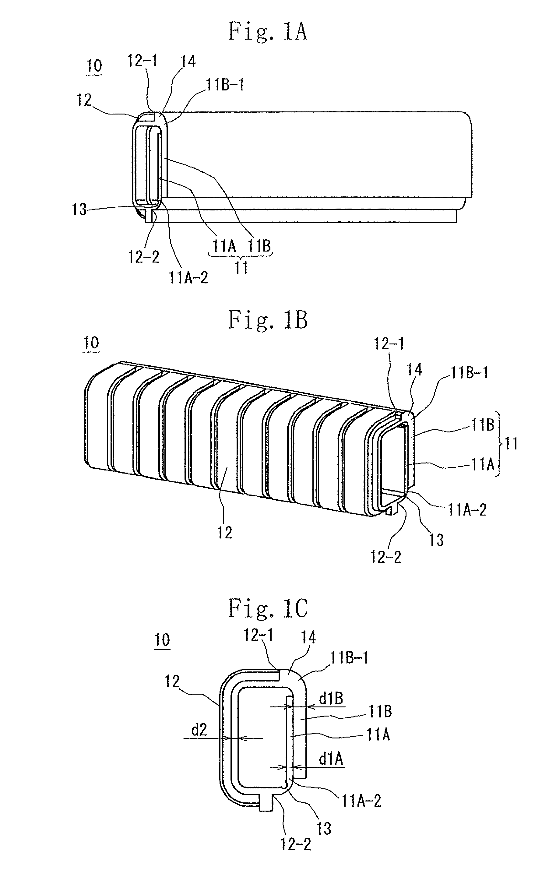
[0059]FIGS. 1 through 3 show the present invention.

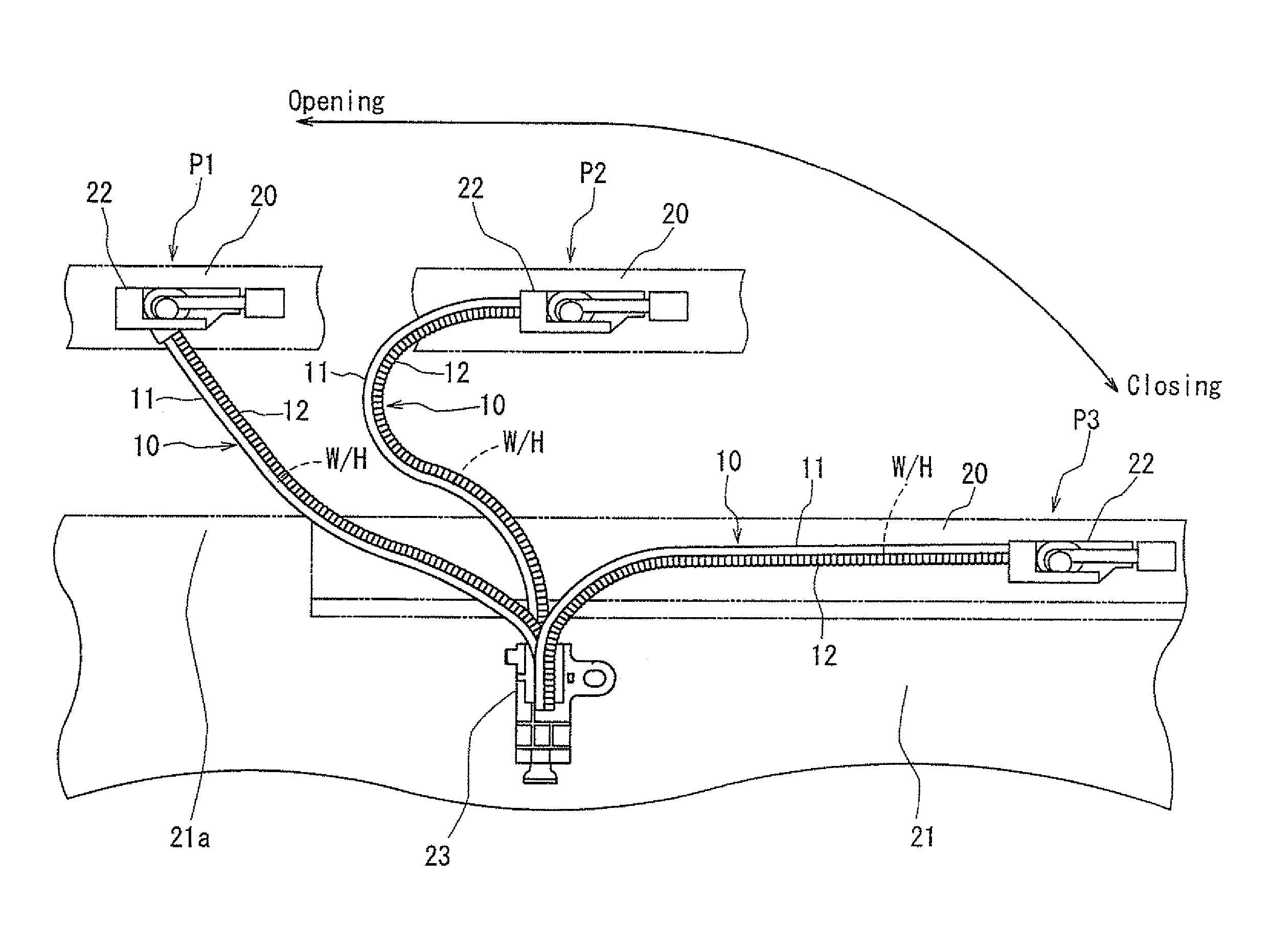
[0060]As shown in FIG. 3, a sheathing protection tube 10 for a wire harness W / H sheathes a wire harness W / H wired between a slide door 20 of a car and a car body 21. Specifically both sides of the wire harness W / H in the longitudinal direction thereof are supported by a slide door-side supporting member 22 and a car body-side supporting member 23, whereas a portion of the wire harness W / H between both sides thereof cross-wired without being supported thereby is sheathed with the sheathing protection tube 10.

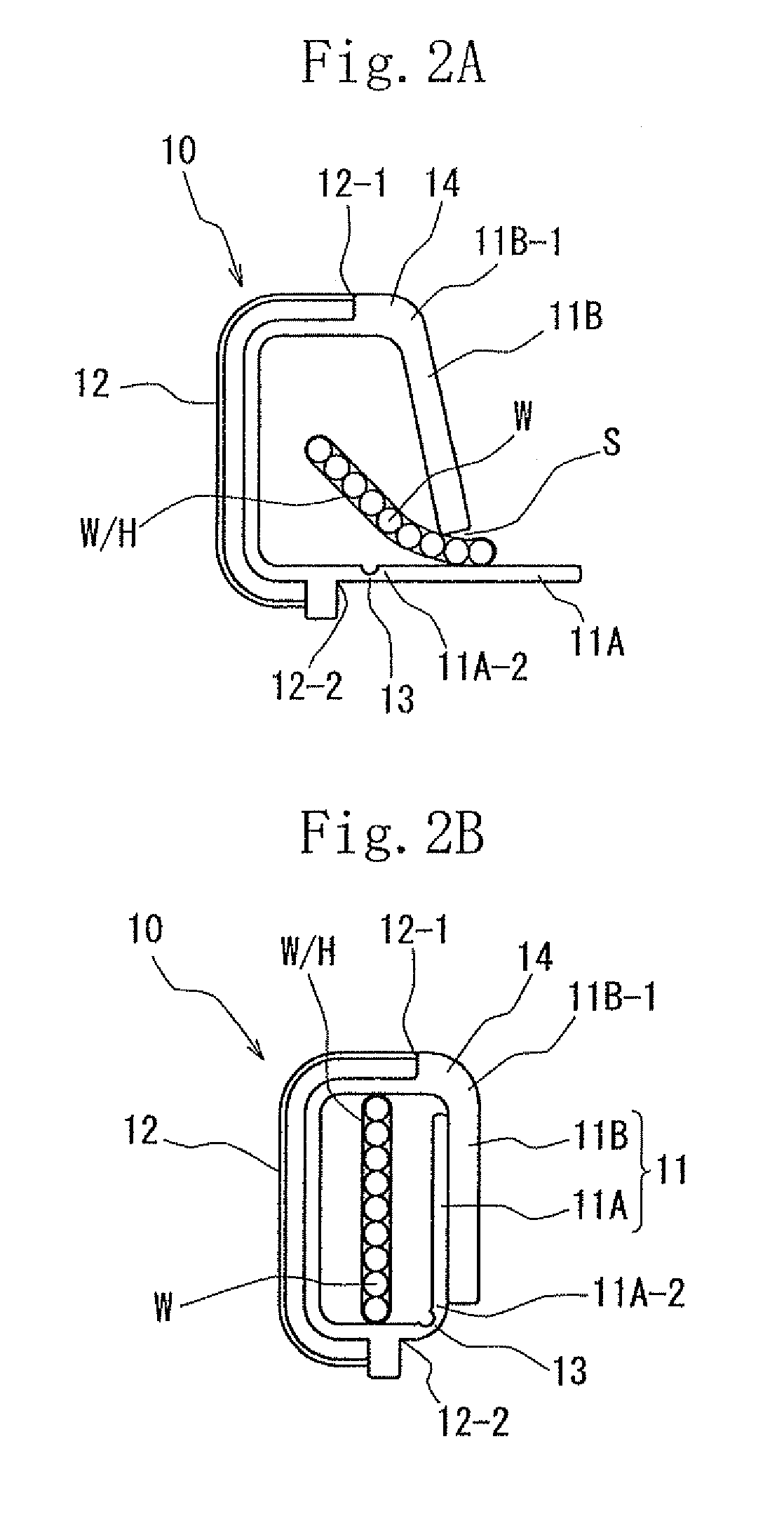
[0061]The sheathing protection tube 10 is formed by molding EPDM. As shown in FIG. 1, the sheathing protection tube 10 has a flat part 11 at one side section thereof extended in a vertical direction and other section continuous with the one side section and sectionally rectangular gutter-shaped to form a sectionally rectangle configuration to insert the wire harness therethrough. The entire other section including a portion there...

second embodiment

[0075]FIGS. 4 and 5 show the

[0076]The second embodiment is similar to the first embodiment except that a bending restriction rib 15 having a thickness of 3 mm is set on the flat part 11 of the sheathing protection tube 10 at a portion thereof disposed in a region A in the vicinity of a fixed end of the car body-side supporting member 23.

[0077]Similarly to the first embodiment, in the second embodiment, it is possible to effectively prevent the cross-wired wire harness W / H from hanging and allow the wire harness W / H to follow a movement of the slide door 20 with the wire harness W / H being smoothly curved. Further as described above, in the region A in which the bending angle is required to be restricted, the bending restriction rib 15 having a large thickness is set on the flat part 11 of the sheathing protection tube 10. Thereby by properly restricting the bending angle of the wire harness W / H, it is possible to securely prevent the wire harness W / H and a tire house 21a from interfe...

third embodiment

[0078]FIG. 6 shows the

[0079]The third embodiment is similar to the first embodiment except that the other section continuous with the one side section is sectionally semicircular ring-shaped.

[0080]In the third embodiment, the wire harness W / H holding bundled electric wires is sheathed with the sheathing protection tube 10.

[0081]Similarly to the first embodiment, in the third embodiment, it is possible to effectively prevent the cross-wired wire harness W / H from hanging and allow the wire harness W / H to follow the movement of the slide door 20 with the wire harness W / H being smoothly curved.


PUM

PropertyMeasurementUnit
thicknessaaaaaaaaaa
thickness d1Aaaaaaaaaaa
thickness d1Baaaaaaaaaa

Abstract

A wire harness exterior protecting tube minimizes sagging of a wire harness laid in a straddling manner in a vehicle and allows smooth bending of the wire harness. The wire harness exterior protecting tube has longitudinal opposite ends supported in a straddling manner by the vehicle without support between the opposite ends. The protecting tube has at one side section a vertical flat plate section and also has the other section having a square U-shaped or semicircular ring-shaped cross-section. The other section connects to the one side section to form a square or semicircular cross-sectional shape. That portion of the other section which faces the flat plate section is a bellows section having a corrugated shape. The thickness of the flat plate section is adapted to suppress the sagging of the protecting tube caused by the weight of the wire harness and to be bendable by bending of the bellows.

Description

TECHNICAL FIELD[0001]The present invention relates to a sheathing protection tube for a wire harness and the wire harness. More particularly the present invention is intended to restrain the wire harness to be cross-wired between a slide door of a vehicle and a vehicle body from hanging and allow the wire harness to perform a smooth curving operation.BACKGROUND ART[0002]The wire harness wired in a vehicle is hitherto protected with various sheathing protection materials to prevent electric wires from interfering with peripheral members and being damaged or broken. For example, as shown in FIG. 7, the annular corrugated tube 1 having the convex portions and the concave portions alternating with each other in its longitudinal direction is disclosed in Japanese Patent Applications Laid-Open No. 2001-258129 (patent document 1). Because the corrugate tube 1 has the construction bendable in all direction, the wire harness is capable of following an operation of a movable member with the w...

Claims


Application Information

Patent Timeline
Patent Type & Authority Patents(United States)
IPC IPC(8): H01B7/00
CPCB60R16/0207B60R16/0215H02G3/0475
Inventor MURAYAMA, SHIGEKI
Owner AUTONETWORKS TECH LTD
Why Eureka
Try Eureka