Fabric filter system

a filter system and fabric technology, applied in the field of fabric filter system, can solve problems such as the difficulty of door operation

Active Publication Date: 2010-03-11
GENERAL ELECTRIC TECH GMBH
View PDF31 Cites 13 Cited by
  • Summary
  • Abstract
  • Description
  • Claims
  • Application Information

AI Technical Summary

Benefits of technology

[0012]The louver-type damper may controllable between an open and a closed position, and may further be controllable to be used in at least one intermediate position between the open and the closed position. This allows the damper to be used not only to shut the gas flow off, but also e.g. to balance the gas flow between parallel filter systems.

Problems solved by technology

One problem associated with such a filter system is that the door may become difficult to operate, particularly if the cross section of the opening is large, such that a large door is to be used.

Method used


Image

  • Fabric filter system
  • Fabric filter system
  • Fabric filter system

Examples


Embodiment Construction

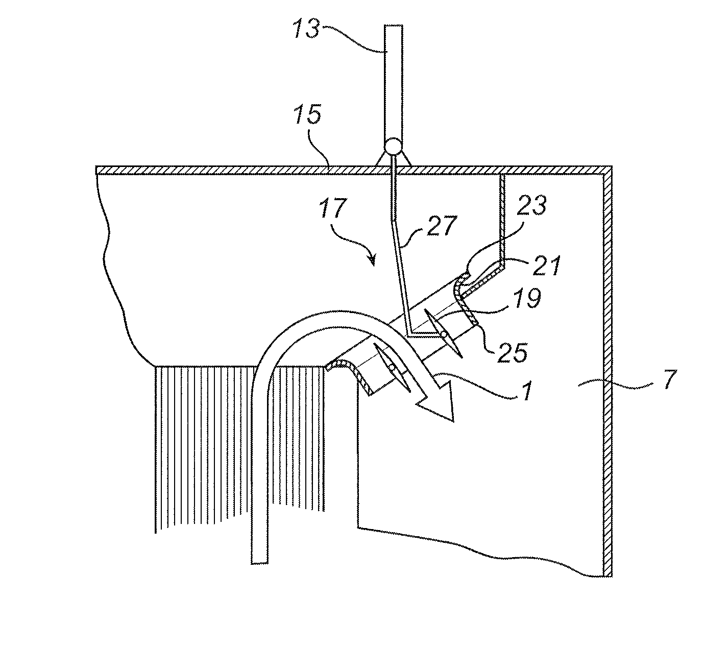
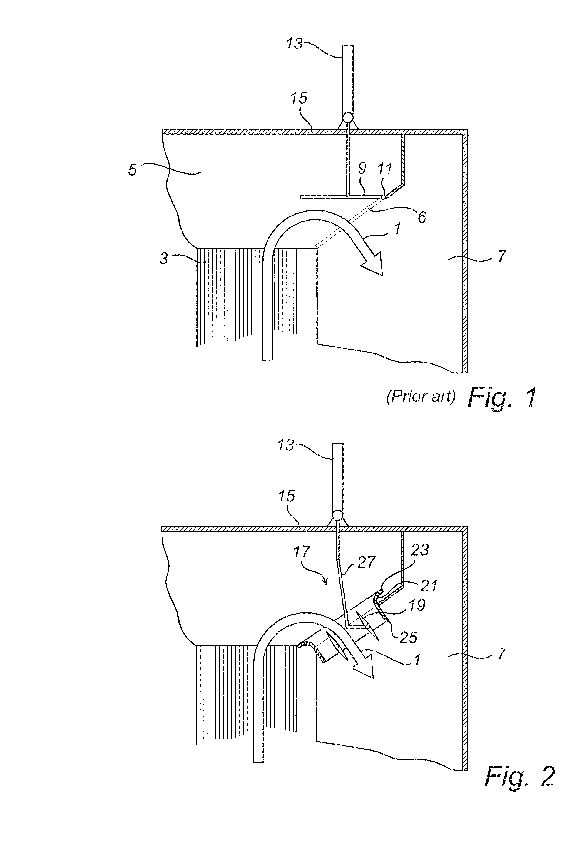
[0020]FIG. 1 shows an outlet part of a fabric filter system according to prior art. Fabric filters in general are well known to the skilled person, and will not be described in detail.

[0021]In general, particulate matter is removed from a gas stream 1 by means of a fabric filter 3 which may comprise a plurality of fabric bags or hoses. In a typical application, the filter system may be used to remove particles from a flue gas stream exiting a combustion chamber in a fossil fuel fired boiler. When exiting the fabric filter 3, the gas passes through a filter plenary space 5 or filter compartment on top of the filter 3. The plenary space is common to a plurality of filter bags. The gas then enters through an opening 6 to an outlet duct 7, which may be placed laterally with respect to the fabric filter 3 and the plenary space 5. A plurality of openings may be provided. The filter system comprises a flow control device in the form of a door-type flap damper 9 for each opening which is pi...


PUM

PropertyMeasurementUnit
forceaaaaaaaaaa
pressure dropaaaaaaaaaa
pressure lossaaaaaaaaaa

Abstract

The present disclosure relates to a fabric filter system, which may be used for removing particulate matter from a gas, such as a combustion process gas. The filter system includes a fabric filter (3) which is placed in a filter compartment. From the filter, gas flows via a filter plenary space (5) to an outlet duct (7), where the gas exits. A flow control device controls the amount of air exiting through the outlet duct. The flow control device comprises a louver-type damper (17). This provides reliable and efficient control of the gas flow. A collar (21), connecting the plenary space (5) with the outlet duct (7), improves the gas flow into the duct.

Description

CROSS-REFERENCE TO RELATED APPLICATION[0001]This application claims the benefit of U.S. Provisional Patent Application Ser. No. 61 / 095,965 filed Sep. 11, 2008, which is hereby incorporated by reference in its entirety.FIELD OF THE INVENTION[0002]The present disclosure relates to a fabric filter system, for removing particulate matter from a gas, comprising a fabric filter, a filter plenary space receiving gas from the fabric filter, an outlet duct, having an interior and through which gas can flow from the filter plenary space, and a flow control device for controlling the amount of gas exiting into the outlet duct.BACKGROUND ART[0003]A general example of a fabric filter system is disclosed e.g. in U.S. Pat. No. 4,336,035. Such a filter may comprise a plurality of filter bags which separate particulate matter from a gas flow. A typical application of such a filter system is to clean flue gases from a coal combustion process.[0004]In some cases it is desired to substantially stop the...

Claims


Application Information

Patent Timeline
Patent Type & Authority Applications(United States)
IPC IPC(8): B01D46/42
CPCB01D46/0047B01D46/0067B01D46/4272B01D46/04B01D46/02B01D46/70
Inventor ANDERSSON, RUNE STENHJELMBERG, ANDERS ERIK MARTIN
Owner GENERAL ELECTRIC TECH GMBH
Why Eureka
Try Eureka