Dynamic local path planning method and system

A local path planning and dynamic technology, applied in the field of robotics, can solve problems such as the inability to consider the attitude of the car at the end of the planned path, many turning points in the final path, and fuzzy logic algorithms.

Pending Publication Date: 2020-10-23
SHANGHAI INST OF MICROSYSTEM & INFORMATION TECH CHINESE ACAD OF SCI
View PDF0 Cites 14 Cited by
  • Summary
  • Abstract
  • Description
  • Claims
  • Application Information

AI Technical Summary

Problems solved by technology

In the application scenario of automatic parking, general local path planning methods such as dynamic window algorithm and fuzzy logic algorithm cannot consider the posture of the car at the end of the planned path, and can only achieve the effect of dynamic obstacle avoidance, while dubin algorithm and reeds-sheep Although the algorithm can consider the terminal pose problem, it can only plan the path without obstacles
Another example is that in a logistics yard, if you want to insert a pallet with a known pose, the existing algorithm cannot dynamically avoid obstacles on the basis of considering the end pose.
[0003] At present, the relatively mature algorithm is the A* algorithm, and its map format also uses a rasterized cost map, but the A* algorithm A* algorithm fixedly adopts the 8-neighborhood expansion method when selecting nodes, and only 8 movement directions can be selected around it. , and the movement angle is limited to an integer multiple of π / 4, which is not conducive to the robot's steering, resulting in more redundant nodes, and the redundant nodes are not optimized, so that the final path has many turning points and is not smooth

Method used


Image

  • Dynamic local path planning method and system
  • Dynamic local path planning method and system
  • Dynamic local path planning method and system

Examples


Embodiment 1

[0050] This embodiment provides a path planning method and system for automatically inserting and removing irregular goods by a forklift. Further, the hardware of the system mainly includes: a forklift, a computer, and a camera. It should be noted that the obstacle avoidance module includes but is not limited to vision sensors.

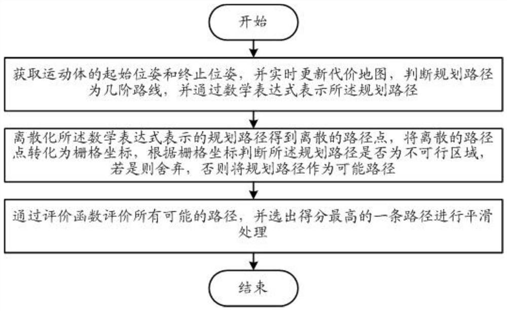
[0051] Such as figure 2 As shown, the dynamic local path planning method specifically includes the following steps:

[0052] Step 1: Obtain the starting pose, ending pose and real-time updated cost map, judge the route of the planned route, and express the route with mathematical expressions.

[0053] When judging the planned route is a few-order route, the first-order path analysis is performed first:

[0054] I. Judging the order of the path

[0055] 1.1 First judge whether d1 and d2 meet the constraint condition d1>R min And d2>R min ;

[0056] In this embodiment, d1=(x v +R min ) 2 +y v 2 ,d2=(x v +R min ) 2 +y v 2 ,Such as imag...

Embodiment 2

[0079] This embodiment provides a path planning method and system for reversing into a warehouse. Furthermore, the hardware of the system is mainly composed of: one car, one industrial computer, and several laser radars.

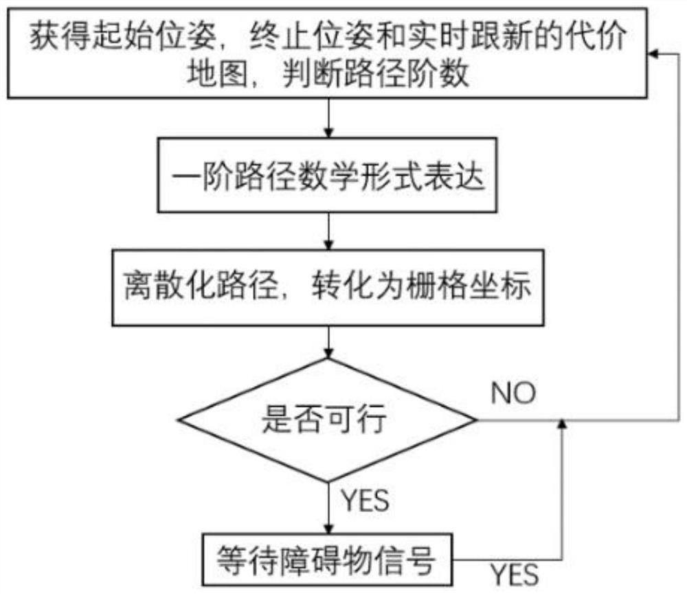
[0080] Such as Figure 4 As shown, the dynamic local path planning method specifically includes the following steps:

[0081] Step 1: Obtain the starting pose, ending pose and real-time updated cost map, judge the route of the planned route, and express the route with mathematical expressions.

[0082] When judging the planned route is a few-order route, the first-order path analysis is performed first:

[0083] I. Judging the order of the path

[0084] 1.1 First judge whether d1 and d2 meet the constraint condition d1>R min And d2>R min ;

[0085] In this embodiment, d1=(x v +R min ) 2 +y v 2 ,d2=(x v +R min ) 2 +y v 2 ,Such as Figure 5 As shown, d1 and d2 represent the current position of the car to (R min ,0) and (-R min ,0) distance, (...

Embodiment 3

[0124] This embodiment provides an embodiment of a three-order path.

[0125] If the path is a third-order path, it means that the position of the moving body does not meet the constraint conditions at this time, and d1min or d2min , it is necessary to find another arc that can be tangent to the second-order route and satisfy the third-order path constraints.

[0126] Third-order path constraints: Among them, θ 3 It is the angle turned by the third section of the arc. RRR type indicates that the first section of the path is clockwise, the second section of the path is clockwise, and the third section of the path is clockwise; LRR type indicates that the first section of the path is counterclockwise, and the second section of the path is clockwise. The second path is clockwise, the third path is clockwise; the RLR type indicates that the first path is clockwise, the second path is counterclockwise, and the third path is clockwise; the LLR type indicates that the first path is...


PUM


Abstract

The invention relates to a dynamic local path planning method which comprises the following steps: obtaining a starting pose and an ending pose of a moving body, updating a cost map in real time, judging that a planned path is a few-order path, and representing the planned path through a mathematical expression; discretizing the planned path represented by the mathematical expression to obtain discrete path points, converting the discrete path points into grid coordinates, judging whether the planned path is an infeasible region or not according to the grid coordinates, if the planned path isthe infeasible region, abandoning the planned path, and otherwise, taking the planned path as a possible path; and evaluating all possible paths through an evaluation function, and selecting the pathwith the highest score to carry out smoothing processing. The invention also relates to a dynamic local path planning system. According to the invention, the planned path curvature is continuous, thecurve is smooth, and the motion characteristics of mobile equipment such as robots or AGVs are met.

Description

technical field [0001] The invention relates to the technical field of robots, in particular to a dynamic local path planning method and system. Background technique [0002] Path planning refers to mobile devices such as robots or AGVs searching for an optimal or suboptimal path from the initial state to the target state according to certain performance indicators (such as distance, time, etc.). According to the degree of mastery of environmental information, it can be divided into two types: (1) global path planning based on environmental prior complete information, also known as static or offline planning; (2) local path planning based on sensor information, also known as dynamic or Online path planning. In the application scenario of automatic parking, general local path planning methods such as dynamic window algorithm and fuzzy logic algorithm cannot consider the posture of the car at the end of the planned path, and can only achieve the effect of dynamic obstacle avo...

Claims


Application Information

Patent Timeline
Patent Type & Authority Applications(China)
IPC IPC(8): G01C21/20G01C21/34G05D1/02
CPCG01C21/20G01C21/3415G01C21/3446G05D1/0214
Inventor 黄敏胡文祥张晓林李嘉茂
Owner SHANGHAI INST OF MICROSYSTEM & INFORMATION TECH CHINESE ACAD OF SCI
Why Eureka
Try Eureka