Shaped cutter surface

a cutter surface and shape technology, applied in the field of drill bits, can solve the problems of cutter failure, common failure modes of cutter chipping, spalling and delaminating, cutter cracking, and many cutters develop cracking, spalling, chipping and partial fracturing, etc., and achieve the effect of reducing the adverse effects of sudden increase in loading

Active Publication Date: 2010-09-21
SMITH INT INC
View PDF29 Cites 41 Cited by
  • Summary
  • Abstract
  • Description
  • Claims
  • Application Information

AI Technical Summary

Benefits of technology

[0021]One aspect of the present invention relates to an ultra hard cutter having a central axis, sides, and a shaped top working surface. In one embodiment the shaped working surface includes a smoothly curved surface having two (2) or more relative high points that are asymmetrically positioned about the central axis of the cutter. According to this aspect of the invention, the shaped working surface acts to reduce certain adverse consequences of suddenly increased loading due to changes in the geological formation or in the manner of drill bit operation. The cutter is useful for drill bits used for drilling various types of geological formations.
[0022]In certain other embodiments, the ultra hard layer of the cutter forms a shaped working surface or is formed to provide a shaped working surface that has a smoothly curved ridge, the crest of the ridge having at least two different heights. According to this aspect of the invention, the smoothly curved ridge acts to direct cuttings or chips of the geological formation with a shearing action and to either side of the ridge, much like a plow. This tends to reduce certain adverse consequences of chips bonding to the surface, to reduce the WOB, and to improve the thermal conduction of heat away from the cutter and the drill bit. The cutter is useful for drill bits used for drilling various types of geological formations.
[0023]According to another aspect of the invention, a cutter has a shaped working surface that includes a first relative peak, or relative high point, inward a short distance from the side of the cutter and adjacent to the intended cutting edge or critical region. A second relative peak, or relative high point, is spaced a second distance from the cutting edge and the first and second relative peaks are interconnected with a smoothly curved concave surface. The shaped working surface facilitates cutting to a first depth in the geological formation with an average back rake angle that varies with the depth of the cut into the geological formation. Particularly, the average back rake angle can be made to increase dramatically with increased depth of cut to increase stability of a drill bit using such cutters. In operation, as the second relative peak begins to engage the geological formation, the average back rake angle is increased due to the shape of the second peak, the WOB increases and the ROP decreases. Thus, when the cutters begin to cut too aggressively or to gouge into the geological formation, the rate of drilling is slowed and stability is increased. Such a shaped working surface can also provide other useful cutting characteristics.

Problems solved by technology

It has been found that cutter chipping, spalling and delaminating are common failure modes for ultra hard flat top surface cutters.
It has been found by applicants that many cutters develop cracking, spalling, chipping and partial fracturing of the ultra hard material cutting layer at a region of cutting layer subjected to the highest loading during drilling.
Cracks of sufficient length may cause the separation of a sufficiently large piece of ultra hard material, rendering the cutter 18 ineffective or resulting in the failure of the cutter 18.
When this happens, drilling operations may have to be ceased to allow for recovery of the drag bit and replacement of the ineffective or failed cutter.
Such a drill bit body is very hard and difficult to machine.
It has been found by applicants that cutters with sharp cutting edges or small back rake angles provide a good drilling ROP, but are often subject to instability and are susceptible to chipping, cracking or partial fracturing when subjected to high forces normal to the working surface.
Cutters with large back rake angles are often subjected to heavy wear, abrasion and shear forces resulting in chipping, spalling, and delaminating due to excessive downward force or weight on bit (WOB) required to obtain reasonable ROP.
Thick ultra hard layers that might be good for abrasion wear are often susceptible to cracking, spalling, and delaminating as a result of residual thermal stresses associated with forming thick ultra hard layers on the substrate.
However, selecting the best bit is not always straightforward because many formations have mixed characteristics (i.e., the geological formation may include both hard and soft zones), depending on the location and depth of the well bore.
Where a drill bit is operated outside the desired ranges of operation, the bit can be damaged or the life of the bit can be severely reduced.
For example, a drill bit normally operated in one general type of formation may penetrate into a different formation too rapidly or too slowly subjecting it to too little load or too much load.
For another example, a drill bit rotating and penetrating at a desired speed may encounter an unexpectedly hard material, possibly subjecting the bit to a “surprise” or sudden impact force.
A material that is softer than expected may result in a high rate of rotation, a high ROP, or both, that can cause the cutters to shear too deeply or to gouge into the geological formation.
This can place greater loading, excessive shear forces and added heat on the working surface of the cutters.
Rotation speeds that are too high without sufficient WOB, for a particular drill bit design in a given formation, can also result in detrimental instability (bit whirling) and chattering because the drill bit cuts too deeply or intermittently bites into the geological formation.
Cutter chipping, spalling, and delaminating, in these and other situations, are common failure modes for ultra hard flat top surface cutters.
It has been found by applicants that while an axially symmetrical shape can provide some additional strength and support to the contact edge at some cutting depth, the cutting efficiency of these cutters may be reduced.
This can result in a corresponding increase in cracking, crack propagation, chipping and spalling.

Method used


Image

  • Shaped cutter surface
  • Shaped cutter surface
  • Shaped cutter surface

Examples


Embodiment Construction

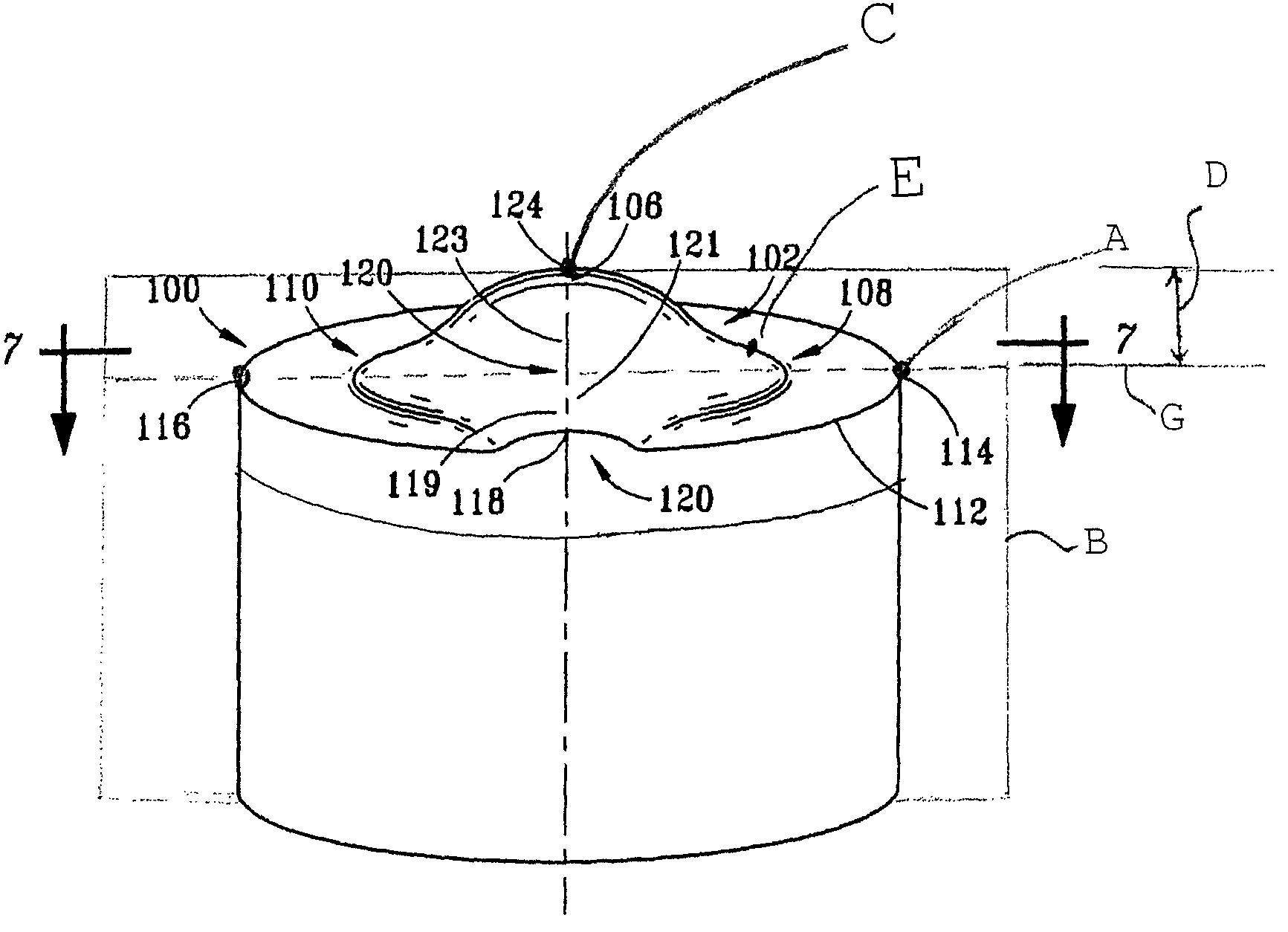
[0132]Embodiments of the present invention relate to cutters having shaped working surfaces. By using such a structure, the present inventors have discovered that such cutters can better withstand high loading at the critical region imposed during drilling so as to have an enhanced operating life. According to certain aspects of the invention, cutters with shaped working surfaces can cut efficiently at designed speed, penetration and loading conditions, and can compensate for the amount of cutting load in changing formations. Such a shaped cutter surface has been found to increase the strength of the cutter edges in response to increased cutting depth, and according to certain aspects of the invention, to increase the strength of the cutter edges proportionally to the increased load associated with increased depth of cutting. Such a shaped cutter surface has been found to provide efficient chip removal. Such a shaped cutter surface has also been found to increase stability. Such a s...


PUM


Abstract

A cutter for a drill bit used in a geological formation includes a shaped ultra hard working surface. The cutter with the shaped working surface is mounted on a drill bit to provide desired cutting characteristics. The shaped working surface provides varied cutting characteristics depending upon the shape, and the characteristics can vary depending upon the depth of the cut.

Description

[0001]This application claims priority, pursuant to 35 U.S.C. §119(e), to U.S. Provisional Patent Application No. 60 / 566,751 filed Apr. 30, 2004, U.S. Provisional Patent Application No. 60 / 584,307 filed Jun. 30, 2004, and U.S. Provisional Patent Application No. 60 / 648,863, filed Feb. 1, 2005. Those applications are incorporated by reference in their entireties.BACKGROUND OF INVENTION[0002]1. Field of the Invention[0003]The invention relates generally to drill bits in the oil and gas industry, particularly to drill bits having cutters or inserts having hard and ultra hard cutting surfaces or tables and to cutters or inserts for drill bits such as drag bits and, more particularly, to cutters and inserts with ultra hard shaped working surfaces made from materials such as diamond material, polycrystalline diamond material, or other ultra hard material bonded to a substrate and / or to a support stud.[0004]2. Background Art[0005]Rotary drill bits with no moving elements on them are typical...

Claims


Application Information

Patent Timeline
Patent Type & Authority Patents(United States)
IPC IPC(8): E21B10/42E21B10/36E21B10/46E21B10/56E21B10/567E21B10/573
CPCE21B10/5673E21B10/5735E21B10/46
Inventor SHEN, YUELINZHANG, YOUHEYONG, ZHOU
Owner SMITH INT INC
Why Eureka
Try Eureka