Laser processing method of vortex light beam

A laser processing method and vortex beam technology, applied in metal processing equipment, laser welding equipment, manufacturing tools, etc., can solve the problems of poor cutting section quality and low processing efficiency, achieve good section quality, low cost, and improve flexibility sexual effect

Pending Publication Date: 2022-08-05
FOSHAN HONGSHI LASER TECH CO LTD
View PDF12 Cites 0 Cited by
  • Summary
  • Abstract
  • Description
  • Claims
  • Application Information

AI Technical Summary

Problems solved by technology

Therefore, the existing technology has the problems of low processing efficiency and poor cutting section quality.

Method used


Image

  • Laser processing method of vortex light beam
  • Laser processing method of vortex light beam
  • Laser processing method of vortex light beam

Examples


Embodiment 1

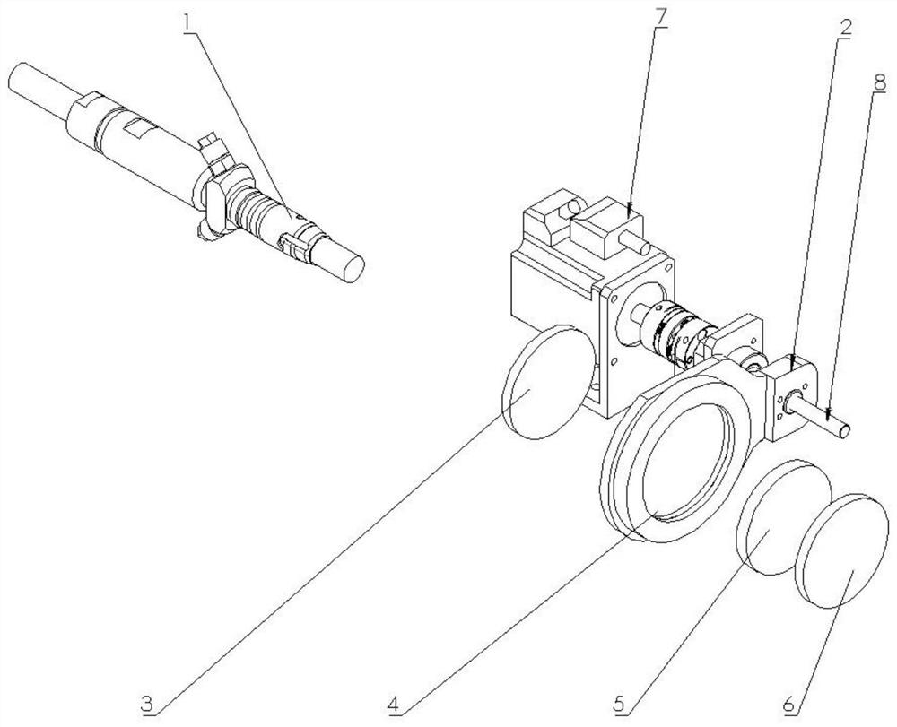
[0056] refer to figure 1 and figure 2 , a laser processing method of a vortex beam, using a laser processing equipment, the laser processing equipment includes a light source element 1, a collimating mirror element 3, a vortex phase plate 4, an axicon mirror 5, a Fourier lens 6 and a control components. The light source element 1 is a light source fiber, and the light source element 1 is used for emitting a Gaussian beam. The light source element 1 , the collimating mirror element 3 , the vortex phase plate 4 , the axicon 5 and the Fourier lens 6 are arranged in sequence along the beam propagation direction. The control assembly includes a motor 7, a lead screw 8 and a mounting seat 2. The output shaft of the motor 7 is fixedly connected to the lead screw 8. The mounting seat 2 is threadedly connected to the lead screw 8 and is used to install the scroll phase plate 4. The mounting seat 2 is connected to the motor 7. Relative translation, so that the motor 7 can drive the ...

Embodiment 2

[0087] A laser processing method of a vortex beam adopts a laser processing equipment, the laser processing equipment comprises a light source element, a collimating mirror element, a vortex phase plate, an axicon mirror, a Fourier lens and a control assembly, and the light source element is used for The Gaussian beam is emitted, the light source element, the collimating mirror element, the vortex phase plate, the axicon mirror and the Fourier lens are arranged in sequence along the beam propagation direction, and the control component is connected with the vortex phase plate and is used to control the passing through the vortex phase plate. the polarization vector of the beam;

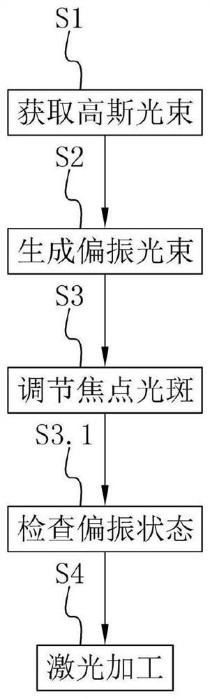
[0088] The laser processing method of vortex light speed includes the following steps:

[0089] S1. Obtain a Gaussian beam: the light source element emits a Gaussian beam, and the Gaussian beam passes through the collimator element and then irradiates the vortex phase plate.

[0090] S2. Generate a p...


PUM

PropertyMeasurementUnit
wavelengthaaaaaaaaaa

Abstract

According to the vortex beam laser processing method, laser processing equipment is adopted, and the laser processing equipment comprises a light source element, a collimating lens element, a vortex phase plate, an axicon and a Fourier lens. The light source element, the collimating lens element, the vortex phase plate, the axicon and the Fourier lens are sequentially arranged along the light beam propagation direction; the laser processing method for the vortex light velocity comprises the following steps of obtaining a Gaussian beam, generating a vortex beam, adjusting a focus spot and performing laser processing. The laser cutting device has the beneficial effects that laser cutting machining is conducted through the vortex light beams polarized in the radial direction and the angular direction, the cutting efficiency can be effectively improved, better section quality can be obtained, and the laser cutting device can be suitable for metal machining with the high depth ratio.

Description

technical field [0001] The invention relates to the technical field of laser processing methods, in particular to a laser processing method of a vortex beam. Background technique [0002] Laser processing uses the energy of light to achieve a high energy density at the focus after being focused by a lens, and is processed by the photothermal effect. The form used is a combined lens form, and the material is processed by a Gaussian beam. How to optimize the phase and energy distribution of the overall characteristics of the beam space transmission has become the optimization and research direction of the laser processing technology. [0003] The Chinese invention patent application document with the announcement number CN113770548A discloses a laser processing system, a laser processing method and a method for obtaining an elliptical light spot. In the above laser processing system, the phase of the light beam is modulated by setting the first phase modulation element and t...

Claims


Application Information

Patent Timeline
Patent Type & Authority Applications(China)
IPC IPC(8): B23K26/073B23K26/70
CPCB23K26/073B23K26/702Y02P70/10
Inventor 杜斌常勇
Owner FOSHAN HONGSHI LASER TECH CO LTD
Why Eureka
Try Eureka