Calibration device, calibration method and monitoring system

A technology of calibration device and calibration method, which is applied in the direction of measuring devices, instruments, scientific instruments, etc., can solve the problems of unachievable calibration, inaccurate calibration, low work efficiency, etc., and achieve the goal of not easy to deviate, high precision, and improve work efficiency Effect

Active Publication Date: 2016-06-08
上海创塔电子科技有限公司
View PDF6 Cites 0 Cited by
  • Summary
  • Abstract
  • Description
  • Claims
  • Application Information

AI Technical Summary

Problems solved by technology

[0004] The monitoring instrument needs to be calibrated regularly, so as to ensure the normal operation of the instrument and determine whether there is a fault. In the prior art, the calibration of the monitoring instrument needs to be manually calibrated on site, which is not only extremely inefficient, but also due to manual intervention. , also makes the calibration inaccurate, and limited by the environment, the calibration cannot be achieved

Method used


Image

  • Calibration device, calibration method and monitoring system
  • Calibration device, calibration method and monitoring system
  • Calibration device, calibration method and monitoring system

Examples


Embodiment 1

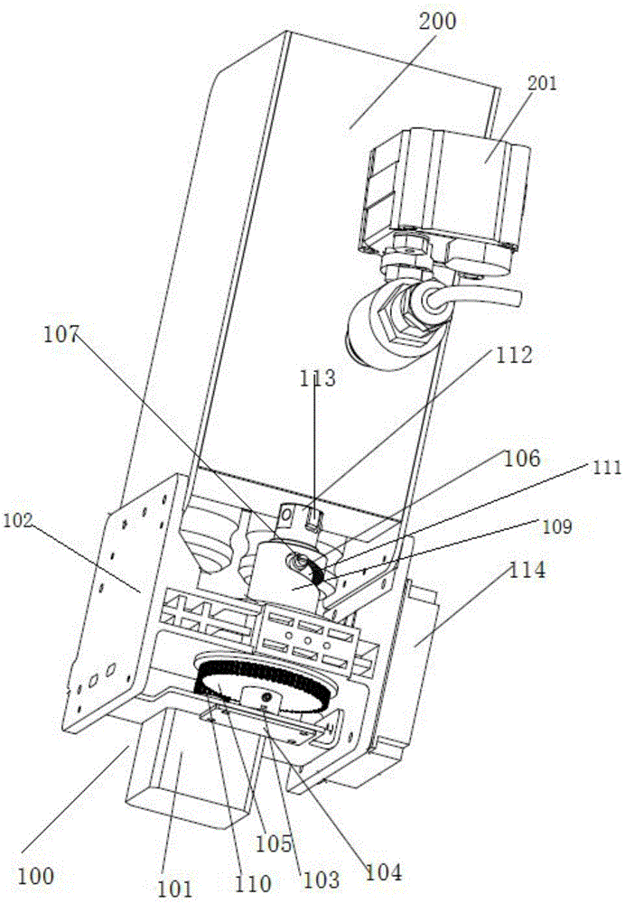
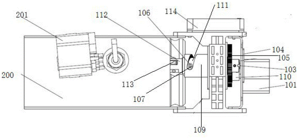
[0051] Such as figure 1 , figure 2 As shown, the embodiment of the present invention provides a calibration device 100, including: a motor 101, an assembly bracket 102, a magnet 103, an encoder 104, a large gear 105, a pinion 110, a transmission shaft 109, a chute 106, and a connector 111, slide block 107 and control panel 114,

[0052]The motor 101 and the encoder 104 are fixed on the assembly bracket 102, the motor 101 is connected to the axis of the pinion 110, the pinion 110 meshes with the teeth of the bull gear 105 to form a linkage gear, and the transmission shaft 109 passes through the axle of the bull gear 105 And be fixedly connected with big gear. Transmission shaft 109 is closed at one end and open at one end. The large gear 105 is located at the closed end of the transmission shaft 109. The magnet 103 is fixed at the shaft center of the closed end of the transmission shaft 109. The transmission shaft 109 has a chute 106 near the open end. The device 111 extend...

Embodiment 2

[0068] Such as figure 1 , figure 2 As shown, the embodiment of the present invention also provides a monitoring system, including a calibration device 100 and a monitoring instrument 200, the calibration device 100 and the monitoring instrument 200 are connected through the connector 111, and the calibration device 100 can realize the monitoring instrument 200 is automatically calibrated.

[0069] The calibration device 100 in the embodiment of the present invention is the same as the calibration device provided in the first embodiment, and will not be repeated here.

[0070] In one embodiment of the present invention, the part of the monitoring instrument 200 connected with the calibration device 100 is provided with a standard scatter plate knob 113, by rotating and pushing the standard scatter plate knob 113, the standard scatter plate can be moved to the monitoring position or built-in a specific Location.

[0071] In one embodiment of the present invention, the monito...

Embodiment 3

[0076] An embodiment of the present invention provides a calibration method, using the calibration device shown in Embodiment 1, including the following steps:

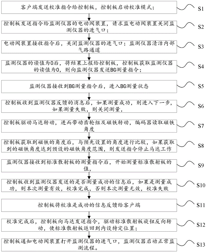
[0077] S1. The client sends a calibration command to the control board, and the control board starts the calibration mode;

[0078] The client can be the background management system of the monitoring system, and can regularly or periodically calibrate the monitoring instrument. When calibration is required, a calibration command is sent to the control board to start the calibration mode. In another embodiment of the present invention, the client It can also be referred to as a host computer, where the host computer or client can be a computer or other smart device, which can be used to send control signals to the control board and receive monitoring parameters returned by the control board.

[0079] S2. The control board sends an instruction to the electric valve of the monitoring instrument, requesting the electric ...


PUM


Abstract

An embodiment of the present invention provides a calibration device, a calibration method, and a monitoring system, wherein the calibration device includes a power device, a transmission device, an encoder, a magnet and a control board, and the power device drives the transmission device to rotate; The magnet is fixedly installed on the shaft center at one end of the transmission device; the encoder reads the rotation angle of the magnet; the control board is electrically connected with the power device and the encoder respectively. The calibration device, calibration method and monitoring system provided by the embodiments of the present invention can realize the automatic calibration function of the monitoring instrument.

Description

technical field [0001] The present invention relates to the field of environmental monitoring, in particular to a calibration device, a calibration method and a monitoring system Background technique [0002] At present, monitoring instruments are needed around urban construction such as large office buildings, shopping malls and other large public facilities to monitor the surrounding environment, such as harmful gases in the air, toxic substances in rainwater, and various germs in the surrounding environment. Some large-scale factories, especially around industrial and mining enterprises that are prone to environmental pollution, such as chemical plants, mining sites, power plants, pharmaceutical factories, and around major construction sites, warehouses with dust and other substances, etc., also need monitoring instruments for real-time monitoring The surrounding environment, and timely transfer the data to the client, if there is an abnormality in the surrounding environ...

Claims


Application Information

Patent Timeline
Patent Type & Authority Patents(China)
IPC IPC(8): G01N33/00
Inventor 罗德平
Owner 上海创塔电子科技有限公司
Why Eureka
Try Eureka