Standard fastener visual detection mechanism

A standard fastener and visual inspection technology, applied in the direction of measuring devices, optical testing defects/defects, instruments, etc., can solve the problems of low detection efficiency, inability to detect thread pitch, and narrow application range, etc., to improve detection efficiency, Reduced equipment investment and good versatility

Inactive Publication Date: 2014-11-12
CHONGQING YINGQUAN STANDARD PARTS
View PDF9 Cites 0 Cited by
  • Summary
  • Abstract
  • Description
  • Claims
  • Application Information

AI Technical Summary

Problems solved by technology

[0006] First, the detection mechanism can detect fewer functions, and the scope of application is narrow
For example, thread detection can only detect the presence or absence of tapping, whether the length is sufficient, etc., but cannot detect whether the thread pitch and tooth shape are qualified, and the detection accuracy is not high, and there are still high defective products after detection
[0007] Second, a detection device can only detect one type of part. Standard fastener companies generally produce a variety of parts, such as screws, nuts, bolts, etc. If automatic detection devices are used, multiple sets of different detection devices must be purchased. Device testing, enterprise production investment increased
The detection disk of the existing detection device needs to make a detection disk corresponding to each specification of the part, and the corresponding detection disk should be replaced when the parts of different specifications are to be tested, which causes problems such as increased cost of the detection device and low detection efficiency
[0009] Fourth, the existing detection device only detects defective products, and 1-2 workers are required to pack the parts that pass the test. The problems of work efficiency and labor cost of the enterprise have not been completely resolved.

Method used


Image

  • Standard fastener visual detection mechanism
  • Standard fastener visual detection mechanism
  • Standard fastener visual detection mechanism

Examples


Embodiment Construction

[0029] Below in conjunction with accompanying drawing and embodiment the present invention will be further described:

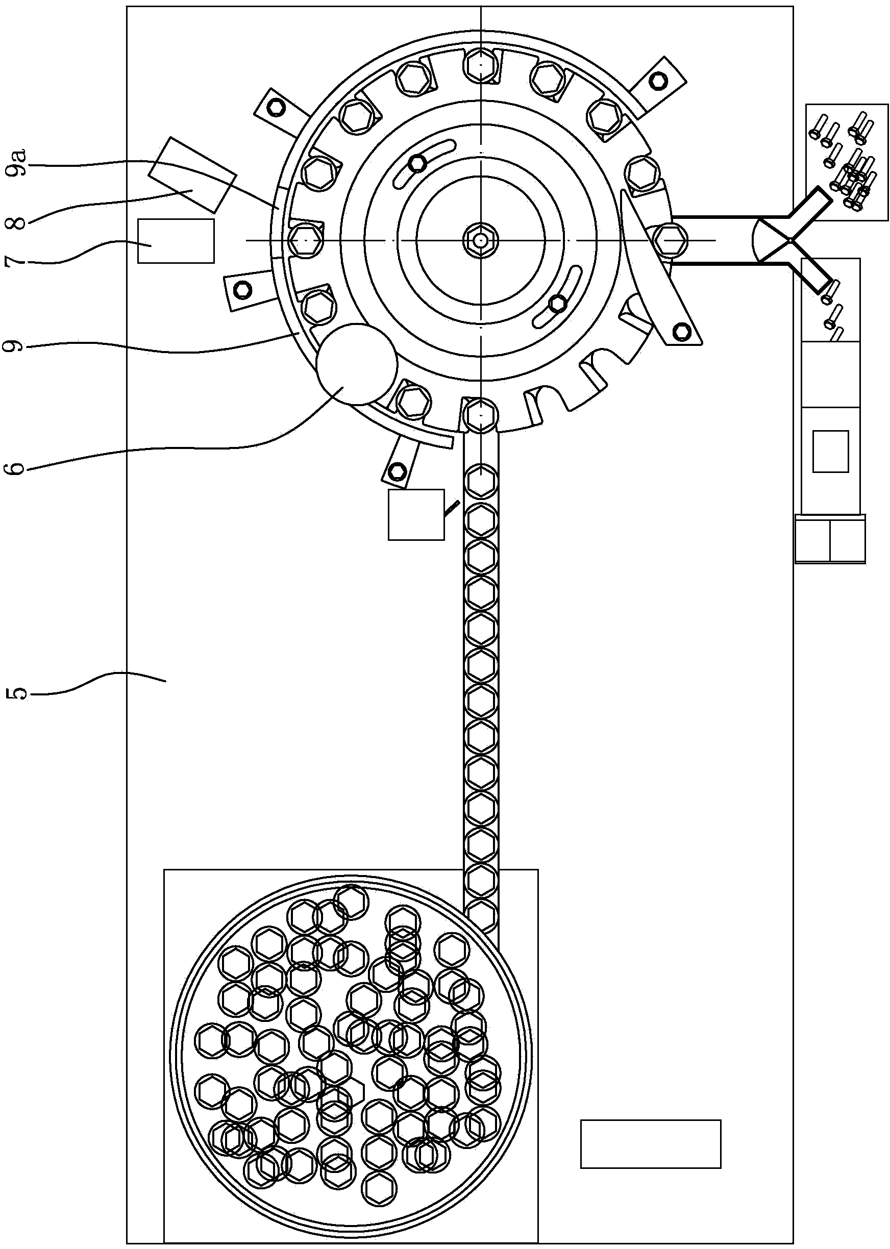
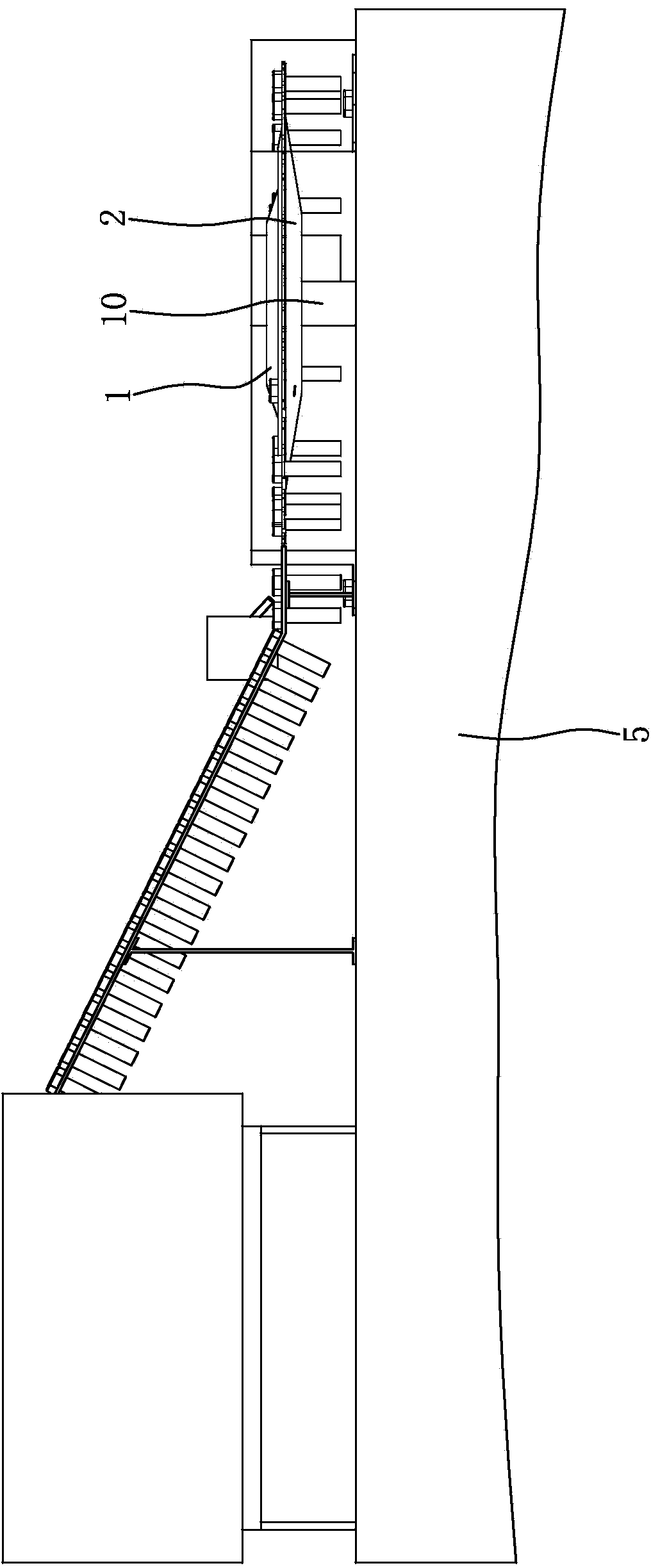
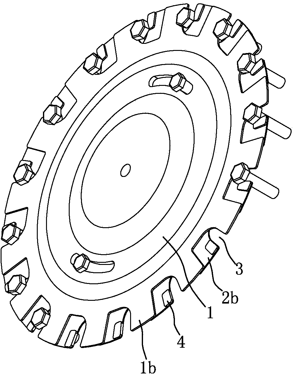
[0030] Such as figure 1 , figure 2 , image 3 , Figure 4 , Figure 5 , Figure 6As shown, the indexing turntable is arranged on the machine platform 5 and consists of a moving plate 1 and a fixed plate 2 . The moving plate 1 and the fixed plate 2 are disc structures with equal diameters, and the moving plate 1 is located directly above the fixed plate 2 . The middle part of the top surface of the moving disk 1 is integrally formed with a stepped boss with a small upper part and a larger lower part; The surfaces are fitted together, and the moving plate 1 and the fixed plate 2 are connected by two fastening bolts evenly distributed on the circumference. The hole on the moving plate 1 for the fastening bolts to pass through is an arc-shaped hole 1c, and the hole 1c The center of circle is on the axis line of moving disk 1. A stepper motor 10 is arrang...


PUM


Abstract

The invention discloses a standard fastener visual detection mechanism. An indexing rotary disc is arranged above a machine table (5). The indexing rotary disc is driven by a stepping motor (10) installed on the machine table (5) to rotate. A first CCD camera (6) is arranged above the edge of the indexing rotary disc. A second CCD camera (7) and a third CCD camera (8) are arranged near the indexing rotary disc. One half of the periphery of the indexing rotary disc is surrounded by a disengagement preventing baffle (9) which is in a circular arc shape, and the two ends of the disengagement preventing baffle (9) and the position close to the middle of the disengagement preventing baffle (9) are fixed to the machine table (5) through a support. The standard fastener visual detection mechanism is simple and compact in structure, small in size, low in cost, capable of effectively preventing parts to be detected from being disengaged and taking pictures of the parts from different angles with the three CCD cameras, capable of being used for detecting the various standard fasteners, suitable for different specifications of parts to be detected and good in universality, effectively reduces equipment investment and greatly improves detection efficiency.

Description

technical field [0001] The invention belongs to the technical field of detection devices, and in particular relates to a visual detection mechanism for standard fasteners. Background technique [0002] In recent years, foreign countries have done a lot of research on the use of machine vision technology for quality inspection, and obtained many important results. Visual inspection has the advantages of non-contact, fast speed, high precision, strong anti-interference ability, etc. It has an important application prospect in modern manufacturing industry. With a wide range of applications, visual inspection technology provides an ideal means to solve online measurement problems. In the 1980s, the American National Bureau of Standards made a prediction based on the survey: 80% of the industrial inspection work in the future will be completed by visual inspection technology. [0003] As basic parts, standard fasteners are widely used in many industries of the national economy...

Claims


Application Information

Patent Timeline
Patent Type & Authority Applications(China)
IPC IPC(8): G01N21/88G01B11/00B07C5/34
Inventor 王咏真
Owner CHONGQING YINGQUAN STANDARD PARTS
Why Eureka
Try Eureka