Electricity generation device and method

A kind of equipment and technology for generating equipment, applied in the field of high-efficiency devices, can solve problems such as poor utilization of heat energy, and achieve the effects of reducing the number of parts, simplifying fluid handling, and high cost

Inactive Publication Date: 2014-11-26
HIGHVIEW ENTERPRISES LTD
View PDF7 Cites 4 Cited by
  • Summary
  • Abstract
  • Description
  • Claims
  • Application Information

AI Technical Summary

Problems solved by technology

[0012] A major constraint on the efficiency of such systems and devices is the poor utilization of the thermal energy released from the cryogenic fluid during heating to ambient temperature

Method used


Image

  • Electricity generation device and method
  • Electricity generation device and method
  • Electricity generation device and method

Examples


Embodiment Construction

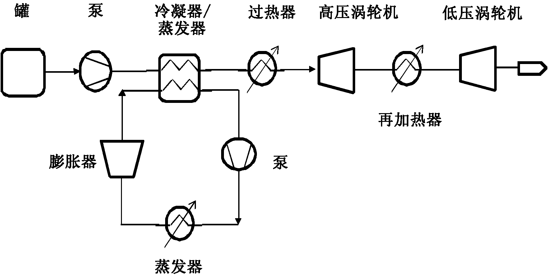
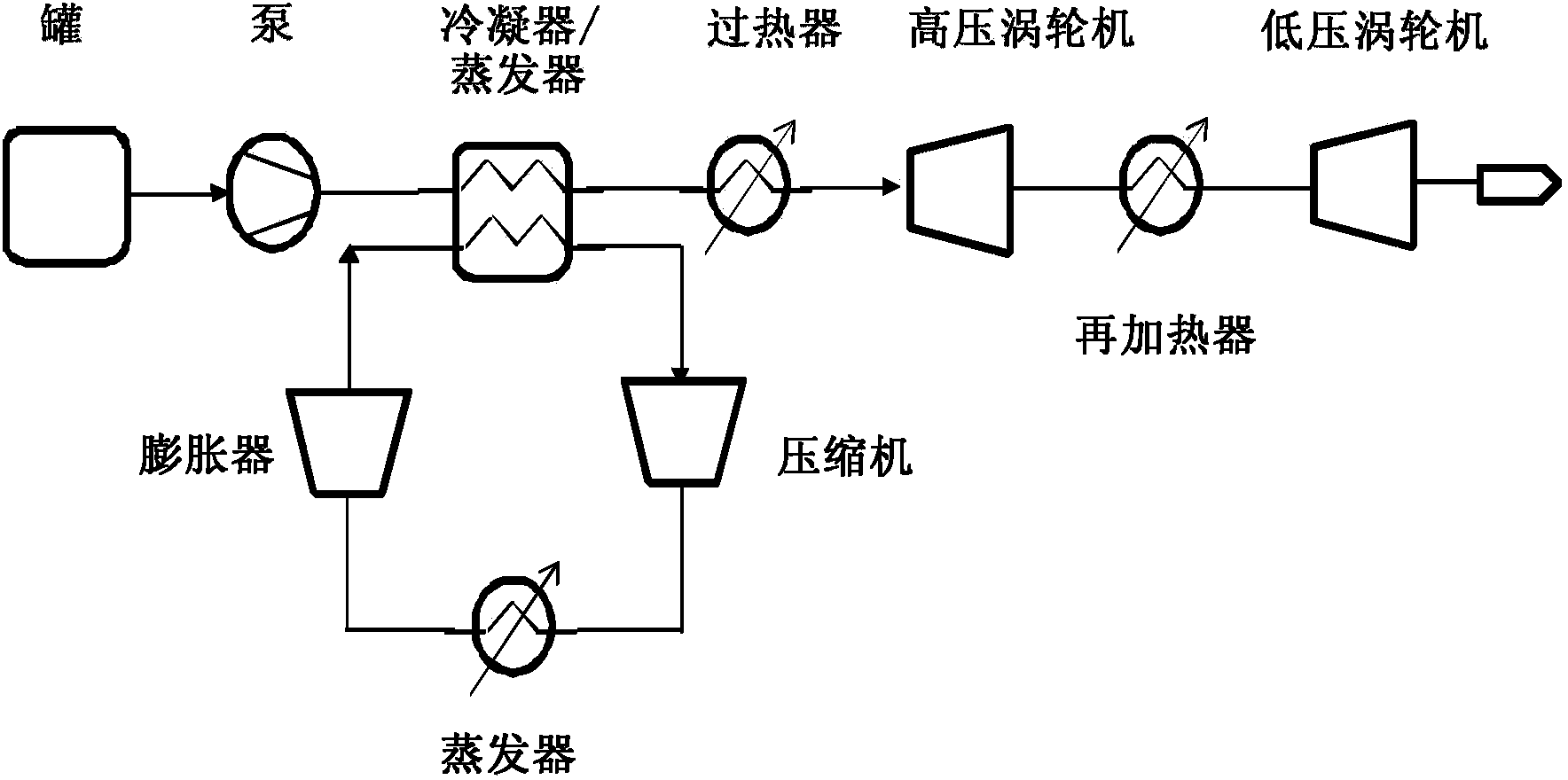
[0052] Figure 4 The first embodiment of the invention shown in FIG. 2 consists of a cryogenic storage tank 400 from which a cryogenic or working fluid is delivered to a high pressure pump 410 . Cryogenic fluids are compressed to high pressures of at least 50 bar, and more usually in excess of 100 bar. This high pressure fluid is then heated in a heat exchanger 420 called an evaporator, where heat energy is transferred between the low temperature working fluid from the tank and the low pressure working fluid in the Brayton circuit of the combined cycle. Optionally, in superheater 430, further heat is added from a co-located waste heat source 480, such as cooling water from a power station. The resulting high pressure fluid, now gaseous if the pressure is below the critical pressure, or liquid if the temperature and pressure conditions are supercritical, is expanded through the first high pressure turbine 440 from which work is extracted. The exhaust from the high pressure tu...


PUM


Abstract

A electricity generation device and a method of generating electricity using the device, which has a tank 400 for storing a cryogenic fluid, such as liquid air or nitrogen, which is then compressed by a pump 410 and delivered to an evaporator 420 which transforms the high pressure cryogenic fluid to a high pressure gas, a first expansion turbine 440 then extracts work from the gas before it is reheated using ambient or waste heat 450 and used to drive a second turbine 460. After the second turbine a portion of the gas is exhausted 490 while the rest is fed to heat the evaporator before it is compressed 470 and fed into the first re-heater. In preferred arrangements there are included further expansion turbines, re-heaters and compressor stages.

Description

technical field [0001] The present invention relates to power generation plants and methods using cryogenic fluids, such as liquid nitrogen or liquid air, and low-grade waste heat sources, and means for increasing the efficiency of energy recovery from such plants. Background technique [0002] The distribution network (or grid) is usually supported by a fleet of diesel generators and open cycle gas turbines that provide power during periods of high demand and during periods of emergency such as unexpected failures of power stations . These generating sources, also commonly referred to as peaking power plants, burn fossil fuels inefficiently and can be a considerable source of atmospheric pollutants. Services provided by these peak power plants include, but are not limited to: [0003] Balance the difference between supply and demand at different times of the day and quickly; [0004] Provide the power required to power the auxiliary equipment required to restart the gene...

Claims


Application Information

Patent Timeline
Patent Type & Authority Applications(China)
IPC IPC(8): F02C1/05F02C1/08F02C6/14
CPCF05D2220/60F02C1/08F02C6/14F02C1/05F01K25/10F02C1/04F01K7/025F01K7/22F01K25/00F01K25/103
Inventor 约翰·丹尼尔·阿拉斯泰尔·哈里斯罗伯特·摩根斯蒂芬·加雷斯·布雷特
Owner HIGHVIEW ENTERPRISES LTD
Why Eureka
Try Eureka