Dead-zone compensation method for parabolic current control

A dead-time compensation and current control technology, applied in the direction of converting irreversible DC power input to AC power output, electrical components, and output power conversion devices, which can solve the constant and dead-time compensation that affects the switching frequency of current tracking accuracy. Technology can not be used and other problems, to achieve the effect of improving the accuracy of current tracking

Active Publication Date: 2014-12-10
STATE GRID CORP OF CHINA +2
View PDF6 Cites 3 Cited by
  • Summary
  • Abstract
  • Description
  • Claims
  • Application Information

AI Technical Summary

Problems solved by technology

In order to avoid the straight-through of the bridge arm, a certain dead time is usually set before the switching tube is turned on. The addition of the dead time will affect the tracking accuracy of the current and the constant switching frequency.
[0004] Existing dead zone compensation techniques cannot be used in parabolic current control

Method used


Image

  • Dead-zone compensation method for parabolic current control
  • Dead-zone compensation method for parabolic current control
  • Dead-zone compensation method for parabolic current control

Examples


Embodiment Construction

[0031] The present invention will be further described below in conjunction with the accompanying drawings and embodiments.

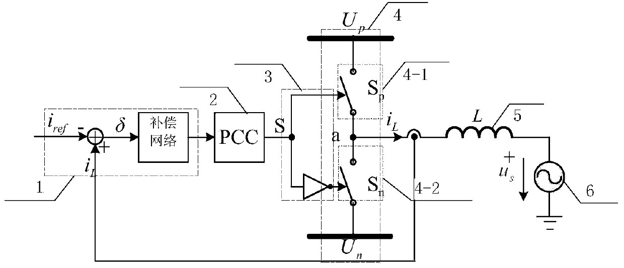
[0032] Such as Figure 4 As shown, a dead zone compensation method of parabolic current control, the compensation circuit used includes a dead zone compensator, a parabolic current controller, a PWM signal generating unit, a drive circuit, a voltage converter bridge arm, an inductor, a load or The power supply and the dead zone compensator are connected with a direction detection unit and an offset generation unit, and the steps include:

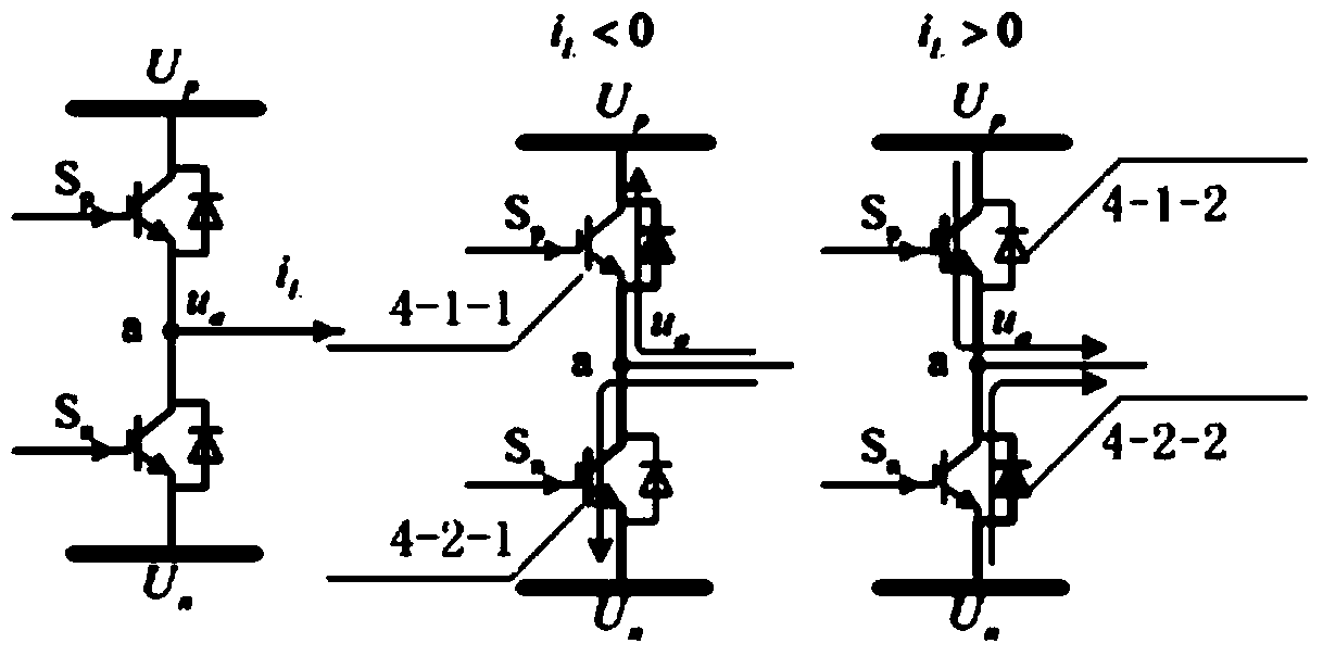
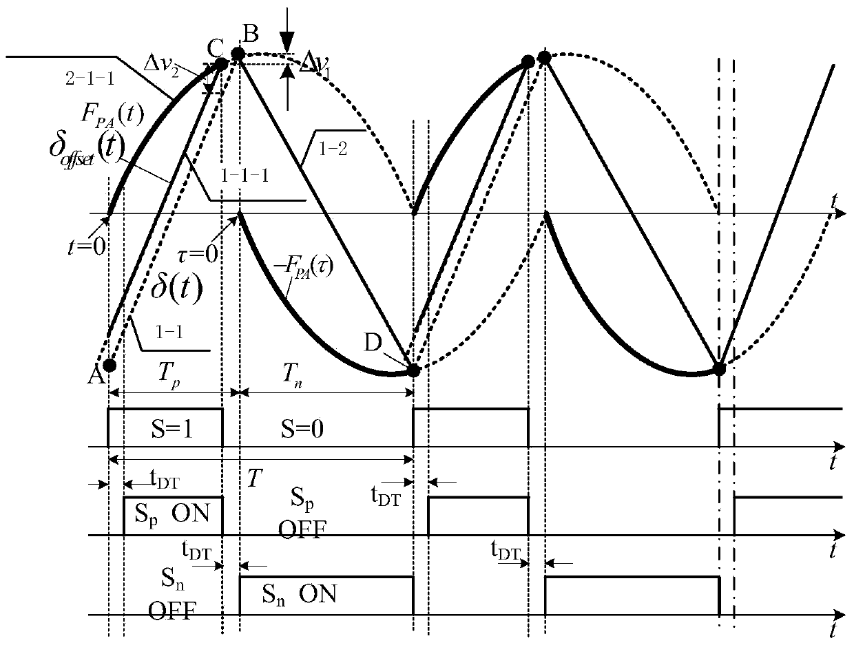
[0033] (1) The direction detection unit detects the output current direction of the converter, and determines that the rising or falling part of the current error signal needs to be adjusted; the offset generation unit generates the required offset;

[0034] (2) The dead zone compensator combines the output current direction and offset, superimposes the corresponding offset on the received current error signal, and g...


PUM


Abstract

The invention discloses a dead-zone compensation method for parabolic current control. An adopted compensating circuit comprises a dead-zone compensator, a parabolic current controller, a PWM (Pulse-Width Modulation) signal generation unit and a driving circuit which are sequentially connected, and the dead-zone compensator is connected with a direction detection unit and an offset generation unit. The dead-zone compensation method for the parabolic current control comprises the steps that the direction detection unit is used for detecting output current direction of a converter to judge a rising or declining portion of current error signals needing to be adjusted; the offset generation unit generates the needed offset; the dead-zone compensator combines the output current direction and the offset to superpose corresponding offset on the received current error signals and generates improved current error signals; the parabolic current controller generates corresponding parabolic carrier waves according to the improved signals output by the dead-zone compensator, the PWM signal generation unit generates corresponding switch signals, on-off action of a bridge arm of a convertor is driven through a driving circuit, and an advanced time interval is set to be dead time to offset the influence of a dead zone.

Description

technical field [0001] The invention relates to a dead zone compensation method of parabolic current control. Background technique [0002] When applying a voltage-type PWM converter that requires high dynamic performance, current tracking control is generally used. Hysteresis loop control is often used in current tracking control, which has high stability and fast response, but the switching frequency varies greatly. [0003] "Pulse Width Modulation Controller with Parabolic Current Tracking" (Patent No.: 200410075770.9) realizes constant switching frequency by introducing a pair of parabolic carriers as the boundary of current error. In order to avoid the straight-through of the bridge arm, a certain dead time is usually set before the switching tube is turned on. The addition of the dead time will affect the tracking accuracy of the current and the constant switching frequency. [0004] Existing dead-band compensation techniques cannot be used in parabolic current contr...

Claims


Application Information

Patent Timeline
Patent Type & Authority Applications(China)
IPC IPC(8): H02M1/08H02M7/48
Inventor 孙逢楠隋国蜀刘耀辉张光辉王传民
Owner STATE GRID CORP OF CHINA
Why Eureka
Try Eureka