Direct-current motor

A technology of DC motors and iron core groups, which is applied in the manufacture of motor generators, electric components, electrical components, etc. It can solve the problems of limited space utilization and increase the overall size, so as to improve power output efficiency, save energy, and flexibly adjust sexual effect

Inactive Publication Date: 2014-12-17
郑全忠
View PDF0 Cites 4 Cited by
  • Summary
  • Abstract
  • Description
  • Claims
  • Application Information

AI Technical Summary

Problems solved by technology

Again, if sufficient power output is required, the external dimensions need to be continuously increased, so the space utilization is limited

Method used


Image

  • Direct-current motor
  • Direct-current motor
  • Direct-current motor

Examples


Embodiment Construction

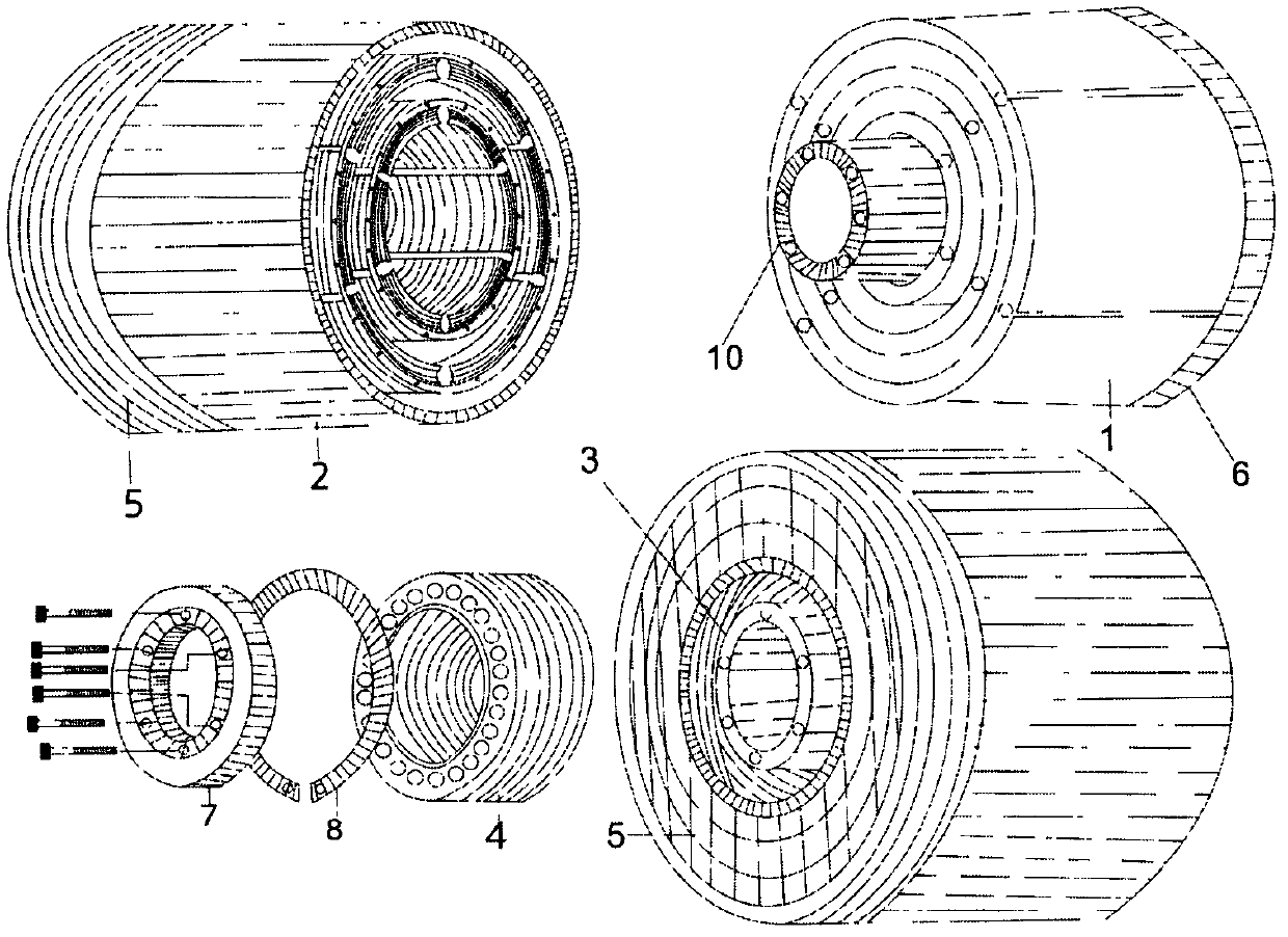
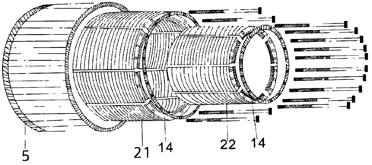
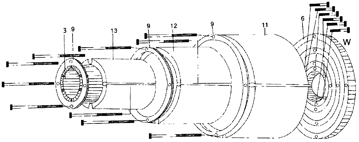
[0018] Firstly, the electromagnetic coil is wound on a single silicon steel sheet core, and then each single iron core is used as a stator core group. A steel ring with screw holes 14 is placed on the whole ring core group, and the stator core group 2 is fixed on the stator base 5 through bolts passing through the screw holes; A ring permanent magnet group, each full ring permanent magnet is provided with a fixed steel ring 9, and each full ring permanent magnet is fixed on the rotor base 6 through a bolt passing through a screw hole; on the back of the base, the connecting shaft 3 and the rotor base 6 fixed.

[0019] Insert the rotor into the stator core based on the concentric axis. Insert bearing 4 in the annular space of stator base 5 and rotor shaft head 10, then clip ring 8 in the annular draw-in groove of stator base 5 and bearing 4 outer edge, prevent bearing 4 from slipping out. On the rotor shaft head 10 with screw holes, put the flange 7 to align with the screw ho...


PUM


Abstract

The invention provides a direct-current motor which comprises a rotor core set, a stator core set, a connecting shaft, a bearing, a stator base, a rotor base and a flange. The rotor core set is coaxially sleeved with the stator core set, the bearing is nested in the annual space between the stator core set base and a rotor shaft head, and a clamping spring is clamped in the annular slot of the stator core set base and the annular slot of the outer edge of the bearing; the flange is connected on the rotor shaft head provided with screw holes and is fixed to the connecting shaft through bolts. By improvement of the physical structure of the motor, utilization rate of the space of the motor is increased, power output efficiency is increased, power generation efficiency can be greatly improved by the motor manufactured in the physical structure, and resources are saved.

Description

technical field [0001] The invention provides a DC motor, in particular to a composite high-efficiency motor. Background technique [0002] Existing DC motors are composed of a single rotor and a single stator. The electromagnetic coil of the rotor or stator is energized to generate an electromagnetic field, and then the carbon brush commutator or brushless control circuit is used to continuously change the magnetic field direction of the electromagnetic coil according to the logic sequence of the rotor rotation, so as to realize the power output of the motor. [0003] Due to the limitations of the structure, this type of motor only generates a magnetic field on a single tangential surface of the rotor and the stator, and the utilization efficiency of electric energy is not very great. Thirdly, if sufficient power output is required, the external dimensions need to be continuously increased, so the space utilization is limited. Contents of the invention [0004] In view ...

Claims


Application Information

Patent Timeline
Patent Type & Authority Applications(China)
IPC IPC(8): H02K16/00H02K1/12H02K1/27H02K15/00
Inventor 郑全忠
Owner 郑全忠
Why Eureka
Try Eureka