Universal infusion head with automatic infusion continuing function

A general-purpose, infusion head technology, applied in the direction of subcutaneous injection devices, devices introduced into the body, etc., can solve the problems of inability to mix soft and hard containers, medical accidents, and inability to use, etc., and achieves easy large-scale promotion, low cost, and structure simple effect

Active Publication Date: 2015-03-04
刘玮
View PDF9 Cites 5 Cited by
  • Summary
  • Abstract
  • Description
  • Claims
  • Application Information

AI Technical Summary

Problems solved by technology

But still be subject to various restrictions in the actual use process, as: this infusion tip can only be used in the container of hard plastic bottle or glass bottle, can not be used in the container of soft bag, more can not be soft, hard container mix
Since soft containers can be used for infusion without air intake, if this scheme is used for continuous infusion of soft bottle groups, that is, when the second or subsequent liquid bottles are soft containers, it may cause the second or subsequent liquids to be output in advance And mixed with the first bottle of liquid, causing a medical accident
Therefore, the infusion group used in this program can only be the first bottle as an infusion bag at most, because the first bottle can be infused regardless of whether it is air-filled or not, and the automatic bottle-changing function starts from the second bottle, and only It is used for hard bottles to achieve the purpose of continuous infusion

Method used


Image

  • Universal infusion head with automatic infusion continuing function
  • Universal infusion head with automatic infusion continuing function
  • Universal infusion head with automatic infusion continuing function

Examples


Embodiment

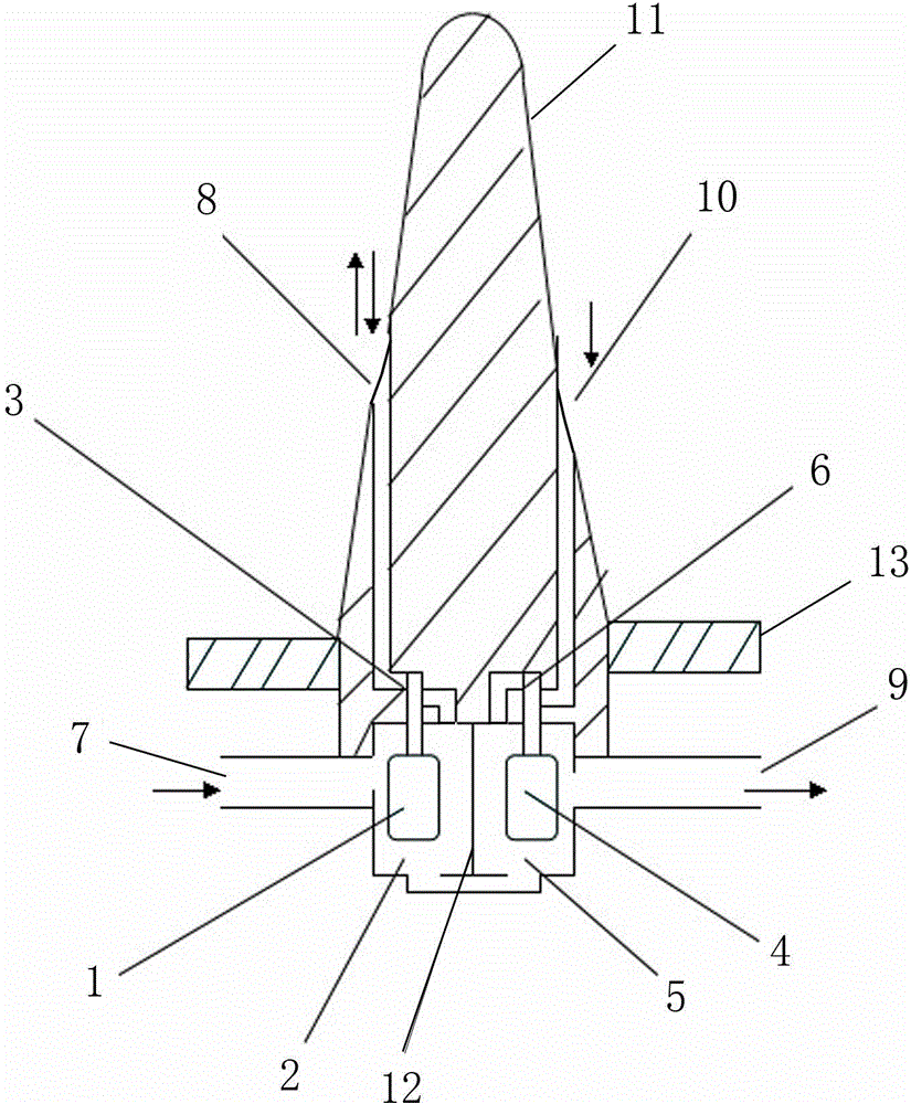
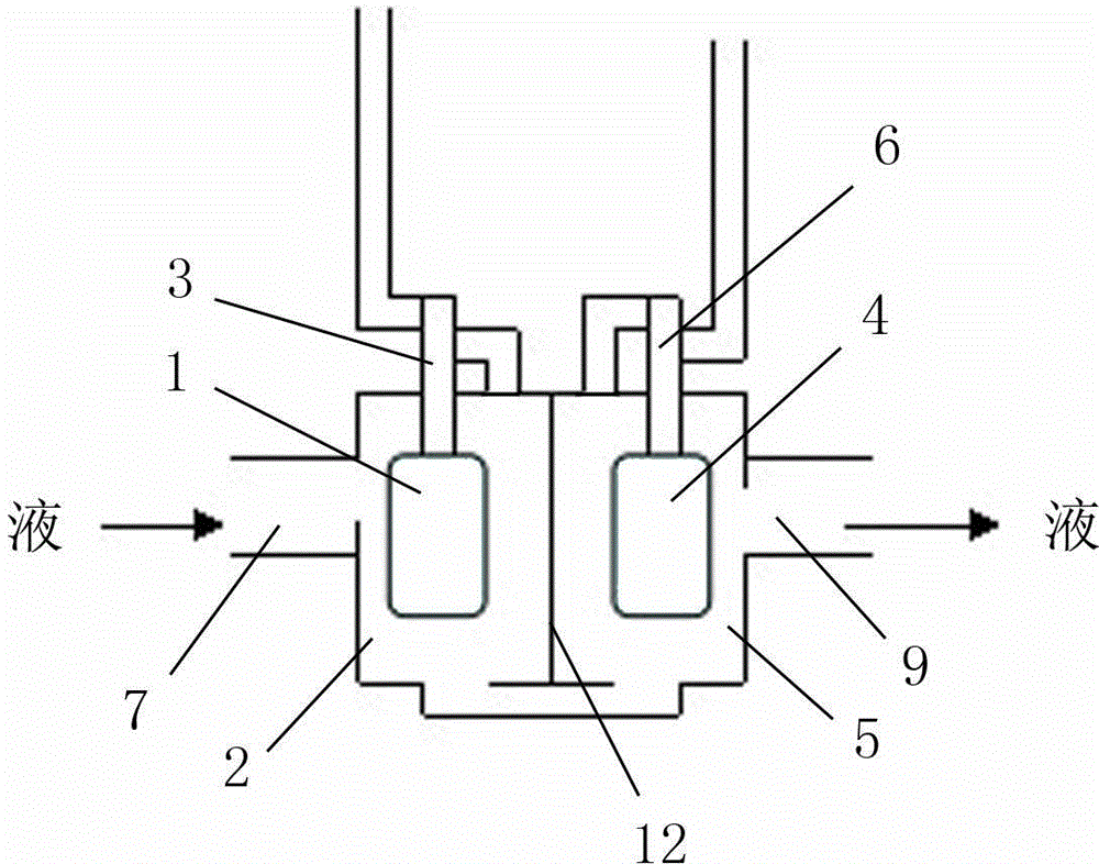
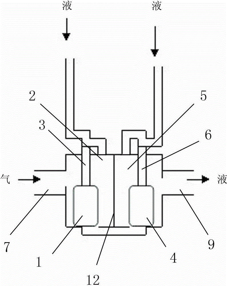
[0025] Such as figure 1 As shown, it includes the first floating ball 1, the first floating valve chamber 2, the first valve 3, the second floating ball 4, the second floating valve chamber 5, the second valve 6, the liquid inlet pipe 7, and the opening of the first infusion channel 8. Outlet tube 9, second infusion channel opening 10, infusion head main body 11, partition 12, handle 13, etc. Wherein the opening 8 of the first infusion channel and the first floating valve chamber 2 are connected to form the first infusion channel, and the tail section of the first infusion channel is in a downward stepped shape (see image 3 , 4 left channel), the first valve 3 is driven by the first floating ball 1 to block or release the first infusion channel; the opening 10 of the second infusion channel connects with the second floating valve chamber 5 to form a second infusion channel, and the second infusion channel The tail segment is concavo-convex (see image 3 , 4 right channel)...


PUM


Abstract

The invention relates to a universal infusion head with an automatic infusion continuing function. The infusion head comprises an infusion head body, two infusion passages and an automatic infusion continuing control chamber. A partition is disposed in the middle of the automatic infusion continuing control chamber to separate the automatic infusion continuing control chamber into a first floating valve chamber and a second floating valve chamber. The bottoms of the first floating valve chamber and the second floating valve chamber are communicated. The first floating valve chamber and the second floating valve chamber respectively correspond to the two infusion passages. A floater valve switch is disposed in each of the first floating valve chamber and the second floating valve chamber. The first floating valve chamber is connected with a liquid inlet tube, and the second floating valve chamber is connected with a liquid outlet tube. The floater valve switch in the two floating valve chambers moves upwards to block the infusion passage of a current bottle or bag by the buoyancy of liquid medicine entering through the liquid inlet tube, and the infusion passage of the current bottle or bag is smooth when the no liquid medicine enters from the liquid inlet tube, air enters the liquid inlet tube, and the floater valve switches naturally fall. The universal infusion head has the advantages that the physical principles of liquid, gas and the floater switches are utilized to achieve automatic infusion continuing of multi-form infusion groups including an infusion bag group, an infusion bottle group or an infusion bottle-bag mixed group, and the application range of continuous infusion devices is widened.

Description

technical field [0001] The invention relates to a medical infusion apparatus, in particular to a general-purpose automatic liquid relay infusion head which utilizes physical principles to automatically control the continuous infusion of an infusion group composed of various types of infusion containers. Background technique [0002] At present, in people's infusion therapy, mostly adopt the single-bottle input, the mode of manually changing the bottle. With the continuous increase of patients, frequent replacement of infusion bottles or infusion bags has brought great labor intensity to medical workers, and medical accidents or doctor-patient disputes are not uncommon due to untimely replacement of bottles during the infusion process. . In order to solve the above problems, some infusion sets for continuous infusion have also begun to appear. But most of these continuous infusion devices are fussy on the infusion tube, and the continuous infusion mostly also needs to be co...

Claims


Application Information

Patent Timeline
Patent Type & Authority Applications(China)
IPC IPC(8): A61M5/175
CPCA61M5/14
Inventor 沈颖惠刘玮刘诗舫沈博宇刘绍勇
Owner 刘玮
Why Eureka
Try Eureka