

Power control method and power control system for hoisting equipment
A technology for lifting equipment and power control, applied in the field of power control systems and power control methods for lifting equipment, can solve problems such as program speed recovery, affecting normal work, and engine inability to adapt
- Summary
- Abstract
- Description
- Claims
- Application Information
AI Technical Summary
Problems solved by technology
Method used
Image

Examples
Embodiment Construction
[0046] The core of the present invention is to provide a power control method for lifting equipment. By changing the way and time when the external load signal is transmitted to the engine, the method makes the engine respond quickly and effectively improves the power adaptability of the engine in low-speed working conditions. In addition, another core of the present invention is to provide a power control system for lifting equipment.
[0047] In order to enable those skilled in the art to better understand the technical solutions of the present invention, the present invention will be further described in detail below in conjunction with the accompanying drawings and specific embodiments.
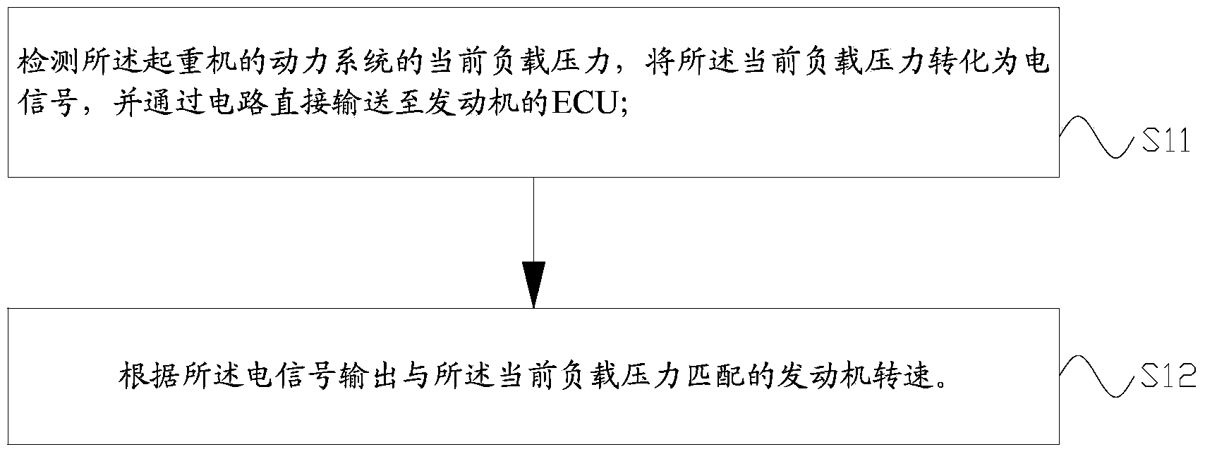
[0048] Please refer to figure 1 , figure 1 It is a flow chart of a specific embodiment of the power control method of the lifting equipment provided by the present invention.
[0049]In a specific embodiment, the present invention provides a power control method of lifting equipment, th...
PUM
 Abstract
Description
Claims
Application Information