Sight of hunting gun

A technology for sights and shotguns, applied to the field of shotgun sights, can solve the problems of cost reduction, occupying space on the barrel or butt, unfavorable compact design, etc., and achieves the effect of saving costs and saving head space

Inactive Publication Date: 2015-03-04
XIAN HUANIC OPTOELECTRONICS CORP
View PDF0 Cites 4 Cited by
  • Summary
  • Abstract
  • Description
  • Claims
  • Application Information

AI Technical Summary

Problems solved by technology

[0002] Existing sights for firearms are generally installed on the barrel through a mounting bracket. This installation method not only takes up space on the barrel or butt, but also requires an additional purchase of a matching mounting bracket, which is not conducive to compactness. Design and Cost Reduction

Method used


Image

  • Sight of hunting gun
  • Sight of hunting gun
  • Sight of hunting gun

Examples


Embodiment Construction

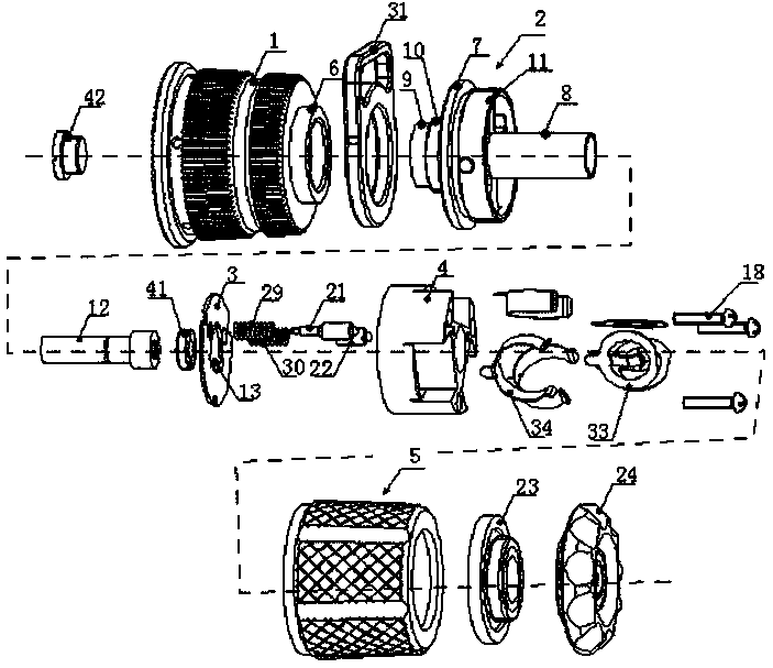
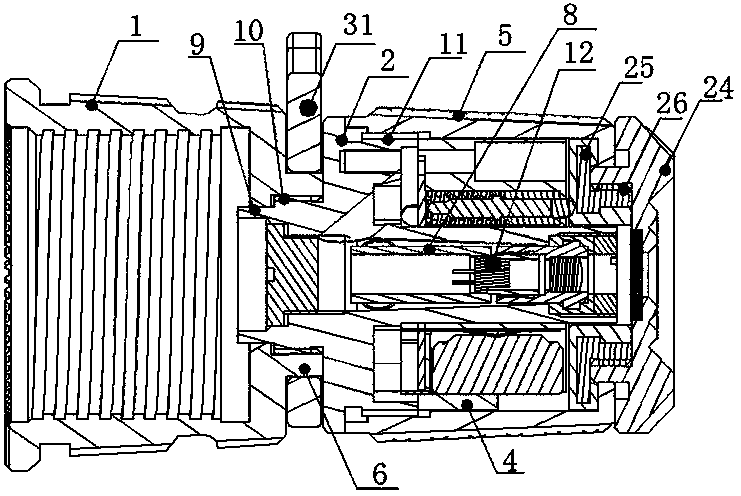
[0043] In order to save the top space of firearms and save expenses, this embodiment provides a figure 1 , 2 The shotgun sight shown includes a fixing seat 1, a laser mounting seat 2, a circuit board 3, a battery seat 4, a switch assembly, and a casing 5 arranged outside the laser mounting seat 2, the circuit board 3 and the battery seat 4, wherein, The rear end of the fixed seat 1 is provided with an internal thread, and the front end surface of the fixed seat 1 is provided with an annular retaining ring 6. The rear end of the laser mounting seat 2 is connected with the annular retaining ring 6, and the annular retaining ring 6 is sleeved with a fixed ring. The strap ring 31 between the seat 1 and the laser mounting seat 2, it is not difficult to see that the fixed seat 1 here actually plays the role of the strap connecting cap on the existing shotgun, that is, it is connected with the shotgun through the internal thread at the rear end. The connection of the bolts, realizes...


PUM


Abstract

The utility model provides a sporting gun sighting device. The sporting gun sighting device comprises a fixed base, a laser device installing base, a circuit board, a battery base, a switch assembly and a shell arranged outside the laser device installing base, the circuit board and the battery base. Internal threads are arranged at the rear end of the fixed base, an annular check ring is arranged on the end face of the front end of the fixed base, the rear end of the laser device installing base is connected with the annular check ring, and the circuit board and the battery base are installed on the laser device installing base; the switch assembly comprises two collision bead switch bodies, an inner cover and a rotary switch body, the two collision bead switch bodies are installed on the battery base, the rear end of the inner cover is installed in the shell and makes contact with the front ends of the collision bead switch bodies, and the front end of the inner cover extends out from the front end of the shell and is connected with the rotary switch body. The sporting gun sighting device can be connected with a gun barrel in a threaded mode and has the function of a strap connecting cap by means of a strap hanging ring; a laser device in the sporting gun sighting device can generate laser for assisting in sighting, and the top space of the gun barrel is saved; it is unnecessary to additionally buy an installing support, and therefore cost is saved.

Description

technical field [0001] The invention belongs to laser measurement technology, in particular to a hunting rifle sight. Background technique [0002] Existing sights for firearms are generally installed on the barrel through a mounting bracket. This installation method will not only occupy the upper space of the barrel or butt, but also need to purchase additional matching mounting brackets, which is not conducive to compactness. Design and cost reduction. [0003] And on the existing shotgun, a strap connecting cap is installed on the lower surface of its gun barrel or the front of the gun stock, and the strap connecting cap is a standing part. Therefore, if the function of the strap connecting cap can be increased to aim or illuminate , will greatly save the space on the top surface of the barrel and save the purchase of mounting brackets, thereby saving money. Contents of the invention [0004] The purpose of the present invention is to save the head space of firearms a...

Claims


Application Information

Patent Timeline
IPC IPC(8): F41G1/46
Inventor 孙建华赵蒙
Owner XIAN HUANIC OPTOELECTRONICS CORP
Why Eureka
Try Eureka