Zigbee network-based direction self-calibration ultrasonic wind measuring system and method

An ultrasonic and self-calibration technology, which is applied in the directions of measuring devices, fluid velocity measurement, velocity/acceleration/impact measurement, etc., can solve the problems of manual calibration direction, inaccurate measurement of wind speed and direction in the required area, etc., and achieve calibration and accurate measurement Effect

Inactive Publication Date: 2015-03-04
SHAANXI NORMAL UNIV
View PDF5 Cites 5 Cited by
  • Summary
  • Abstract
  • Description
  • Claims
  • Application Information

AI Technical Summary

Problems solved by technology

However, the existing ultrasonic anemometers need to consider the influence of the climate environment on the ultrasonic propagation speed when measuring wind speed, and need to manually calibrate the direction, and the single node works alone, so it cannot accurately measure the wind speed and direction in the required area

Method used


Image

  • Zigbee network-based direction self-calibration ultrasonic wind measuring system and method
  • Zigbee network-based direction self-calibration ultrasonic wind measuring system and method
  • Zigbee network-based direction self-calibration ultrasonic wind measuring system and method

Examples


Embodiment Construction

[0025] The present invention is described in further detail below in conjunction with accompanying drawing:

[0026] However, it should be emphasized that the following embodiments are only exemplary and not intended to limit the scope and application of the present invention.

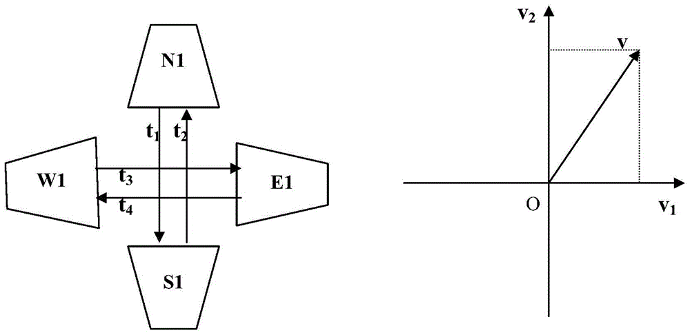
[0027] figure 1 It is a schematic diagram of the installation of the ultrasonic probe provided by the present invention. Ultrasonic probe pair N1S1 (T1T2) and W1E1 (T3T4) are set orthogonally on the same horizontal plane. In the figure, t1t2 is the time from ultrasonic wave N1 to S1 and the time of ultrasonic wave from S1 to N1. The same is true for t3t4. v 1 , v 2 are the wind speed in the WE direction and the wind speed in the NS direction, respectively, and v is the wind speed after synthesis.

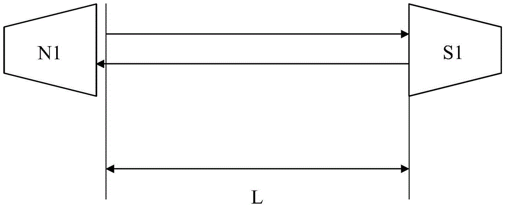
[0028] figure 2 It is the schematic diagram of the wind speed and direction measurement of two pairs of ultrasonic probes in the NS direction. Each N1S1 is equipped with two probes to complete the ult...


PUM


Abstract

The invention provides a Zigbee network-based direction self-calibration ultrasonic wind measuring system and method. A virtual machine coordinate system-based Zigbee network of a topological structure is established through a plurality of Zigbee protocol-based wireless transmission modules; each Zigbee network node comprises two pairs of ultrasonic probes; the probes in each pair are opposite to each other, and the two pairs of ultrasonic probes are vertically arranged in a crossing manner; the wind speeds in two branch directions are calculated by acquiring the propagation time of ultrasonic wave of each pair of probes and the space between two probes; wind speed vectors in the two directions are synthesized to obtain the speed and the direction of natural wind; the actual direction of the natural wind is obtained by acquiring the locating positions of the Zigbee network nodes and the deflection angle of the geomagnetic north pole through an electronic compass.

Description

technical field [0001] The invention relates to an ultrasonic wind measurement system, in particular to a Zigbee network-based self-calibrating ultrasonic wind measurement system and method. Background technique [0002] At present, existing anemometers mainly include mechanical anemometers, heat-sensitive anemometers, and ultrasonic anemometers. Mechanical anemometers have mechanical rotating parts, which have high requirements for the measurement environment. They cannot work normally in environments such as sand, dust, low temperature, and icing, and there are moving parts that are easy to wear and have a short life. Limited by the mechanical structure and measurement principle, the measurement accuracy of the mechanical anemometer is low. [0003] The basic principle of the thermal anemometer is to heat the object placed in the airflow to a certain temperature, and calculate the wind speed by calculating the heat loss of the object. Thermal anemometers are greatly affe...

Claims


Application Information

Patent Timeline
Patent Type & Authority Applications(China)
IPC IPC(8): G01P5/24G01P13/02
Inventor 郭建中李霖刘昕刘世博
Owner SHAANXI NORMAL UNIV
Why Eureka
Try Eureka