Material flow electronic scale

An electronic scale and material technology, which is applied in the direction of continuous material flow weighing equipment, measuring devices, instruments, etc., to achieve the effects of cost economy improvement, additional weight reduction, and weighing accuracy improvement

Active Publication Date: 2015-03-25
SHANDONG SETAQ INSTR
View PDF4 Cites 3 Cited by
  • Summary
  • Abstract
  • Description
  • Claims
  • Application Information

AI Technical Summary

Problems solved by technology

It effectively solves all the problems of the measuring unit of the current sorting scale

Method used


Image

  • Material flow electronic scale
  • Material flow electronic scale
  • Material flow electronic scale

Examples


Embodiment Construction

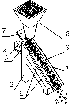
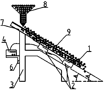
[0031] Such as Figure 1-2 Shown, a kind of material flow electronic scale, it comprises support frame 3 and at least one load cell 2 that is fixedly arranged on support frame 3, is fixedly provided with weighing chute 1 on load cell 2, weighs chute 1 The length direction and the horizontal plane form an angle A, 0°


PUM


Abstract

The invention provides a material flow electronic scale which comprises a supporting frame and weighing sensors fixedly arranged on the supporting frame. A rigid weighing sliding chute is fixedly arranged on the weighing sensors. The material flow electronic scale is characterized in that an angle A is formed between the length direction of the rigid weighing sliding chute and the horizontal plane, and A is larger than zero and smaller than 90 degrees; a rigid material-smoothening sliding chute fixedly arranged on the supporting frame or a feeding device or an independent support is parallel and opposite to the weighing sliding chute at a close distance, does make contact with the weighing sliding chute and is slightly higher than the weighing sliding chute; the bearing ends of the weighing sensors are in rigid connection with the rigid weighing sliding chute, and the designed bearing stress direction of the weighing sensors is perpendicular to the length direction of the rigid weighing sliding chute; the material flow electronic scale is further provided with a weighing control instrument which is electrically connected with the weighing sensors.

Description

technical field [0001] The invention relates to a material flow electronic scale, which is suitable for the weight detection of continuous material flow on a production line. The material stream can be solid or liquid. Background technique [0002] All electronic weighing equipment (including: electronic scales) feel the weight of the object being weighed through sensors. Most electronic weighing devices use force sensors or load cells to measure the local gravity of objects. As we all know, the gravity of an object is perpendicular to the horizontal plane where the object is located. For a long time, when the force sensor or load cell is used, the installation method, force point and direction are strictly specified, so as not to affect the accuracy of the sensor. In order to reduce the component deviation of the sensor, almost all sensor manufacturers, weighing equipment manufacturers, textbooks, weighing industry standards and specifications, training materials, and eq...

Claims


Application Information

Patent Timeline
Patent Type & Authority Applications(China)
IPC IPC(8): G01G11/04G01G11/08
Inventor 汤小牛刘久明
Owner SHANDONG SETAQ INSTR
Why Eureka
Try Eureka