Mini card swiping device

A card-swiping device, a miniature technology, used in instruments, cash registers, etc., can solve the problems of small deformation, difficult to control, and high cost, and achieve the effects of large elastic deformation limit, good card-swiping consistency, and long service life.

Active Publication Date: 2015-04-29
FUJIAN NEWLAND PAYMENT TECH
View PDF6 Cites 1 Cited by
  • Summary
  • Abstract
  • Description
  • Claims
  • Application Information

AI Technical Summary

Problems solved by technology

[0002] Generally, the magnetic head used in POS machines is fixed on a support body, and the magnetic head will move up and down when swiping the card. At this time, the support body will produce a certain amount of deformation during the up and down movement process. The existing support body is generally made flat. The two ends are sleeved on the magnetic head seat through the positioning holes. When the card is swiped, the support body is deformed. After the card is swiped, the magnetic head automatically returns to flatness, and the deformation is small and difficult to control. At this time, the weight of the entire magnetic head structure is concentrated on the magnetic head. , if the POS machine is dropped or shaken, it is easy to cause the overall deformation of the support body, causing the equipment to fail to work normally; in addition, the pillars used to position the two ends of the magnetic head and the structural parts that press the magnetic head require high positional accuracy, otherwise It is easy to cause the gap between the magnetic head and the card swipe block to be too large or too small, resulting in poor card swiping feel; if the structural parts pressing the magnetic head are uneven, it is easy to cause the deformation of the magnetic head shrapnel, the magnetic head and the card swipe block are not parallel, etc., resulting in card swiping Different hand feeling affects the success rate of card swiping
There is another method in the existing technology, that is, the support body does not play an elastic role, and the elastic body is added in addition, the structure process is complicated and the cost is high

Method used


Image

  • Mini card swiping device
  • Mini card swiping device
  • Mini card swiping device

Examples


Embodiment Construction

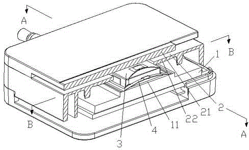
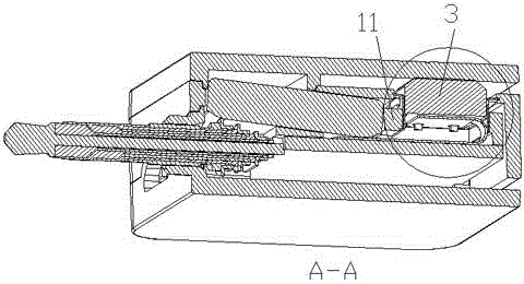
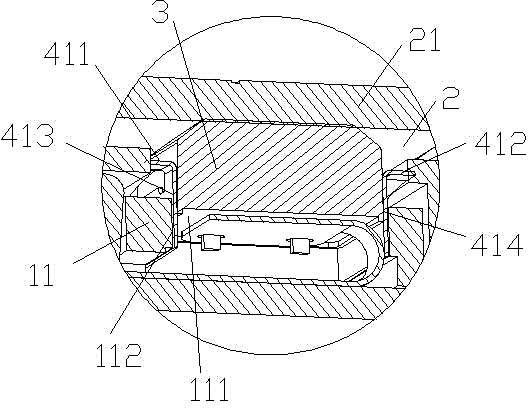
[0023] Such as Figure 1~9 As shown, a miniature card swiping device includes a frame 1, the frame 1 is provided with a card swiping groove 2, and one side of the card swiping groove 2 is provided with a magnetic head 3, and the magnetic head 3 is connected with the frame 1 through a support body , the magnetic head 3 is installed in the middle of the elastic support body 4, the two ends of the elastic support body 4 are embedded in the cavity 5 on both sides of the frame 1 parallel to the card slot 2, and the two ends of the elastic support body 4 are connected The line is parallel to the swiping direction.

[0024] In the present invention, the elastic support body 4 is a frame body 41, and the front side and the rear side of the frame body 41 are provided with a front fixed flap connected to the middle part of the front side 411 and the rear side 412 of the frame body 41. 413 , the rear fixed flap 414 , the magnetic head 3 is installed and connected between the front fixed...


PUM


Abstract

The invention relates to a mini card swiping device comprising a frame. A card swiping slot is formed in the frame. A magnetic head is arranged on side face of the slot, is connected with the frame through a support body and is mounted on the elastic support body. Two ends of the elastic support body are embedded in cavities in two sides of the frame, wherein the cavities are parallel to the card swiping slot, and the connecting line of two ends of the elastic support body is parallel to the card swiping direction. The mini card swiping device is compact in overall structure, reasonable in design of the support body, high in card swiping efficiency and long in service life, and the size of the card swiping device is reduced greatly to enable the magnetic head to be miniaturized.

Description

technical field [0001] The invention relates to a micro card swiping device. Background technique [0002] Generally, the magnetic head used in POS machines is fixed on a support body, and the magnetic head will move up and down when swiping the card. At this time, the support body will produce a certain amount of deformation during the up and down movement process. The existing support body is generally made flat. The two ends are sleeved on the magnetic head seat through the positioning holes. When the card is swiped, the support body is deformed. After the card is swiped, the magnetic head automatically returns to flatness, and the deformation is small and difficult to control. At this time, the weight of the entire magnetic head structure is concentrated on the magnetic head. , if the POS machine is dropped or shaken, it is easy to cause the overall deformation of the support body, causing the equipment to fail to work normally; in addition, the pillars used to position ...

Claims


Application Information

Patent Timeline
Patent Type & Authority Applications(China)
IPC IPC(8): G07G1/12
Inventor 叶滋杰沈思忠林嵘林敏丹
Owner FUJIAN NEWLAND PAYMENT TECH
Why Eureka
Try Eureka