Concrete-filled steel tube column with built-in pre-processed semi-continuous reinforcement cage and its construction method

A technology for concrete filled steel tubular columns and construction methods, applied in the directions of columns, piers, pillars, etc., can solve the problems of narrow construction space, prone to accidents, long operation time, etc., so as to improve fire resistance, reduce the incidence of accidents, reduce The effect of construction difficulty

Active Publication Date: 2017-04-19
姚攀峰
View PDF8 Cites 0 Cited by
  • Summary
  • Abstract
  • Description
  • Claims
  • Application Information

AI Technical Summary

Problems solved by technology

[0004] In the specific implementation process of the above structure, there are the following problems: From the perspective of structural force, the above structure has only the transverse restraint stirrups in the core area, and the large area of ​​concrete has no restraint transverse stirrups. Under the action of external load, among them Department first destroys, as in figure 2 As shown in the figure, it can be seen from the figure that under the action of the external load F, the curvature of the middle part of the deformation curve 12 is very large, and there is a convex belly phenomenon
Then why not add lateral constraints to the large-area concrete to increase its compressive strength? The root cause is that the construction of the reinforcement part of the large-section concrete-filled steel tube column needs to enter the steel pipe, and the construction space for workers entering the steel pipe is narrow and the working time is long. Moreover, the construction site is often prone to accidents due to the cross-operation of multiple types of work.
Therefore, imposing transverse restraints on discretely distributed continuous steel bars in existing large-section CFST columns cannot be implemented on site

Method used


Image

  • Concrete-filled steel tube column with built-in pre-processed semi-continuous reinforcement cage and its construction method
  • Concrete-filled steel tube column with built-in pre-processed semi-continuous reinforcement cage and its construction method
  • Concrete-filled steel tube column with built-in pre-processed semi-continuous reinforcement cage and its construction method

Examples


Embodiment 1

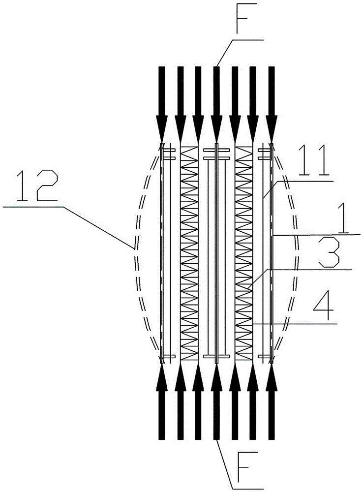
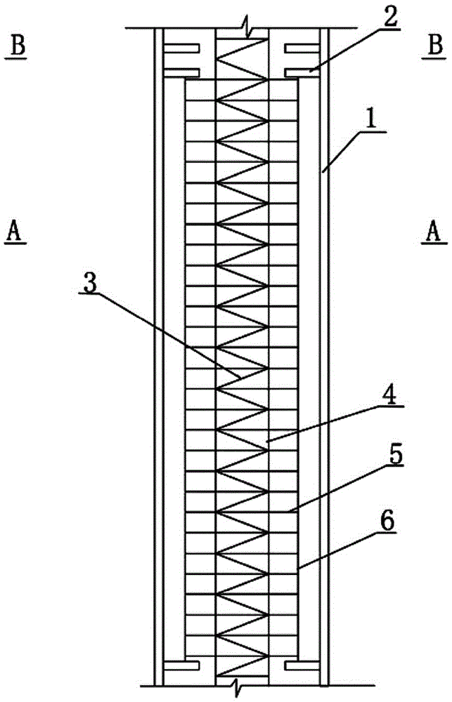
[0047] Embodiment one sees image 3 , Figure 4 , Figure 6 and Figure 7, is a steel tube concrete column with built-in prefabricated semi-continuous steel cage, including a steel cylinder prefabricated with a discontinuous reinforcement cage inside and a continuous reinforcement cage; A whole composed of a giant steel cylinder and a tie piece 8; the interior of the giant steel cylinder is divided into several cavities by vertical vertical partitions 10 and horizontal vertical partitions 9, and horizontal partitions are arranged at intervals along the height direction in each cavity. plate 2, the intermittent steel cage is located between adjacent transverse partition plates 2, and it is connected to the inner wall of the giant steel cylinder through the tie piece 8 to form a whole; the continuous steel cage is arranged along the length of the cavity, and the There is a hole in the middle part of the transverse dividing plate 2 for the continuous reinforcement cage to pass...

Embodiment 2

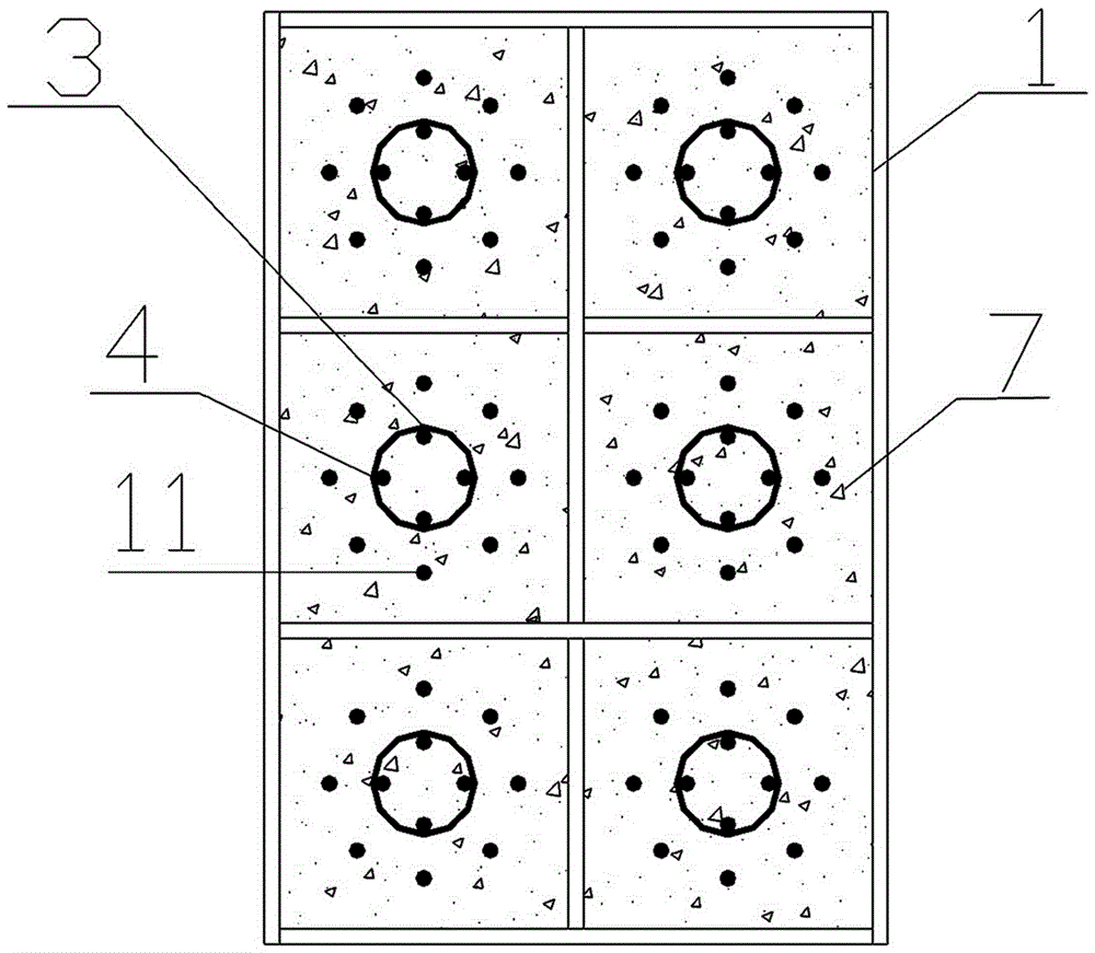
[0057] Embodiment two see Figure 9 , Figure 10 and Figure 13 , and the difference from Embodiment 1 is that the steel cylinder is divided into 6 cavities by the vertical vertical partition 10 and the horizontal vertical partition 9, and the steel cylinder and the cavity are both rectangular in section.

[0058] Both the large stirrups 5 forming the intermittent reinforcement cage and the small stirrups 3 forming the continuous reinforcement cage are circular.

Embodiment 3

[0059] Embodiment three see Figure 9 , Figure 11 and Figure 13 , different from the second embodiment, the large stirrups 5 forming the intermittent reinforcement cage are rectangular, and the small stirrups 3 forming the continuous reinforcement cage are all circular.


PUM


Abstract

The invention relates to a concrete-filled steel tube column with a built-in preprocessed semi-continuous steel reinforcement cage and a construction method of the concrete-filled steel tube column. The steel tube column comprises a steel cylinder of which the interior is prefabricated with an intermittent steel reinforcement cage and a continuous steel reinforcement cage, wherein the steel cylinder of which the interior is prefabricated with the intermittent steel reinforcement cage is an integral body consisting of the intermittent steel reinforcement cage, a huge steel cylinder and a pulling-tying component; the interior of the huge steel cylinder is divided into a plurality of cavities by virtue of a longitudinal vertical separation plate and a transverse vertical separation plate, transverse separation plates are arranged in each cavity at intervals along the height direction, and the intermittent steel reinforcement cage is positioned between the adjacent transverse separation plates and is connected with the inner wall of the huge steel cylinder to form a whole by virtue of the pulling-tying component; and the continuous steel reinforcement cage is fully arranged along the length of each cavity, and holes for the continuous steel reinforcement cage to penetrate through are formed in the middle parts of the transverse separation plates. By adopting the concrete-filled steel tube column disclosed by the application, the technical problems that a super-long huge concrete-filled steel tube column structure is low in compressive strength and poor in fireproof performance can be solved; and the concrete-filled steel tube column can be widely applied to super-high-rise long-span structures.

Description

technical field [0001] The invention relates to a steel pipe concrete column and a construction method thereof, in particular to a steel pipe concrete column with a built-in preprocessed semi-continuous reinforcement cage and a construction method thereof. Background technique [0002] With the continuous increase in the scale of urban buildings and the requirements of anti-seismic technology, more and more concrete-filled steel tube structures are used. The commonly used concrete-filled steel tube structure is the way of outsourcing steel tubes and pouring concrete inside. However, there are some problems in this structural form, such as concrete shrinkage and The problem of creep, especially for large-scale concrete-filled steel pipes, after the concrete with a large internal volume shrinks, there are micro-cracks with the steel pipes, which may cause the concrete and steel pipes to be unable to bear the force at the same time to achieve the predetermined force effect. [...

Claims


Application Information

Patent Timeline
Patent Type & Authority Patents(China)
IPC IPC(8): E04C3/34E04G21/00E04B1/98E04B1/94
Inventor 姚攀峰
Owner 姚攀峰
Why Eureka
Try Eureka