Control circuit and method for switching power converter

A switching power supply and converter technology, applied in the direction of regulating electrical variables, control/regulating systems, converting DC power input to DC power output, etc., can solve the problems of poor output voltage regulation rate, affecting output current control accuracy, etc. Reduce ripple, good constant current characteristics, and simple circuit implementation

Active Publication Date: 2015-06-17
HANGZHOU SILAN MICROELECTRONICS
View PDF4 Cites 11 Cited by
  • Summary
  • Abstract
  • Description
  • Claims
  • Application Information

AI Technical Summary

Problems solved by technology

Under different output voltages, the ratio of the deviation time Toff-Tdis to the demagnetization time Tdis changes, making the output voltage adjustment rate of the output current worse, that is, the output current is different under different output voltages, and also Affects the control accuracy of the output current

Method used


Image

  • Control circuit and method for switching power converter
  • Control circuit and method for switching power converter
  • Control circuit and method for switching power converter

Examples


Embodiment Construction

[0044] The present invention will be further described below in conjunction with specific embodiments and accompanying drawings, but the protection scope of the present invention should not be limited thereby.

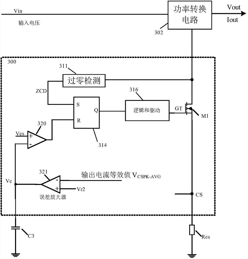
[0045] figure 2 A simplified block diagram of a switching power converter according to an embodiment of the invention is shown. The switching power converter includes a power conversion circuit 302 , a switching power controller 300 and a sampling resistor Rcs. The input voltage Vin of the switching power converter provides an output current Iout to a load through the power conversion circuit 302 . The power conversion circuit 302 may be any suitable power conversion circuit, such as a transformer, an inductor, etc., that can be used to convert an input current / voltage into a desired target current / voltage. The switching power supply controller 300 is used to control the working state of the power conversion circuit 302 . Switching power supply controller 300 may in...


PUM


Abstract

The invention discloses a control circuit and method for a switching power converter. The switching power converter comprises a power conversion circuit, a sampling resistor and a switching power controller. Output currents are provided for the switching power converter through the power conversion circuit. The switching power controller comprises a power switch, an error amplifier, a comparator circuit and a logic and drive circuit. The power switch is used for controlling power supply of the power conversion circuit, and the sampling resistor is coupled to the power switch and provides sampling voltage signals. The error amplifier is used for receiving the output current equivalent value and the preset threshold value of the switching power converter so as to generate error voltages, wherein the output current equivalent value indicates the amplitude of the output currents of the switching power converter. The comparator circuit is used for comparing the sampling voltage signals and the error voltages and generating comparison output signals. The logic and drive circuit is used for generating drive signals, wherein when the comparison output signals generated by the comparator circuit indicate that the sampling voltage signals excess the error voltages, the drive signals switch off the power switch.

Description

technical field [0001] The invention relates to a switching power supply, in particular to a control circuit and a control method for a switching power supply converter. Background technique [0002] Figure 1A A driving circuit of a conventional source-driven buck structure is shown, which can operate in a continuous operation mode and includes a switching power supply controller 100 . Figure 1B shows as Figure 1A The timing diagram of the drive circuit shown in . When the first power switch M1 is turned on and the second power switch M2 is turned on accordingly, the input current generated by the input voltage Vin flows through the output capacitor C1 and the load (for example, an LED) connected in parallel with the output capacitor C1 at the output terminal Vout ), and then flow through the inductor L1, the second power switch M2, the first power switch M1, and the sampling resistor Rcs, wherein the current on the inductor L1 will gradually increase, and the inductor L...

Claims


Application Information

Patent Timeline
Patent Type & Authority Applications(China)
IPC IPC(8): H02M3/156H02M1/14
CPCH02M3/156
Inventor 姚云龙吴建兴
Owner HANGZHOU SILAN MICROELECTRONICS
Why Eureka
Try Eureka