
A Multistage Plunger Super Long Stroke Oil Well Pump
An ultra-long stroke, multi-stage column technology, applied in the direction of pumps, pump components, variable displacement pump components, etc., can solve the problems of easy resistance, no development, and discomfort of rod pumping units, so as to reduce wear and tear. Small gap, solve the effect of plunger stuck
- Summary
- Abstract
- Description
- Claims
- Application Information
AI Technical Summary
Problems solved by technology
Method used
Image

Examples
Embodiment Construction
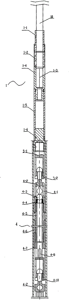
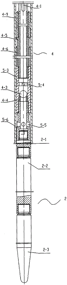
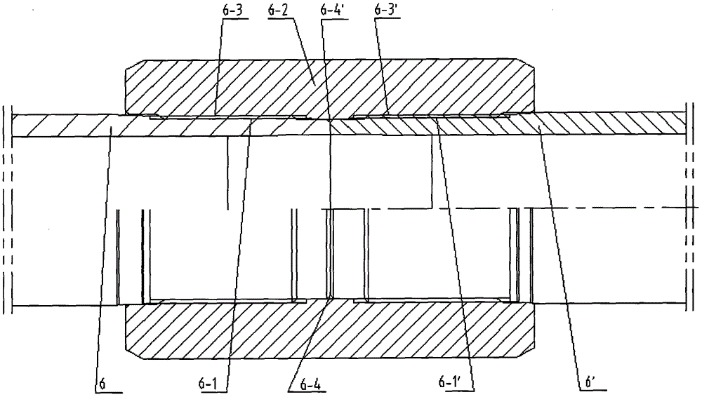
[0014] see Picture 1-1 , Figure 1-2 , image 3 , a multi-stage plunger ultra-long stroke oil well pump is composed of a steel body multi-stage plunger 9 and an ultra-long pump barrel 11; the steel body multi-stage plunger 9 is placed in the ultra-long pump barrel 11; the steel body multi-stage plunger 9 is composed of a sealing cavity part 1, a weight part 2 and a plurality of steel-body single-stage plungers 4 connected in series; a sealing gland 1-1, a sealing glue 1-2 and a pressure rope head 1-3 seal the wire rope 10 The upper section 1-4 of the chamber is compressed, the sealing gland 1-1, the upper section 1-4 of the sealing chamber, the sealing chamber 1-5, and the upper variable diameter 1-6 are threaded in turn, and the sealing ring is sealed to form the seal of the plunger. Cavity part 1; the number of serially connected weighting rods 2-2 is determined by the need for counterweight, and the lower variable diameter 2-1, multiple weighting rods 2-2, and the lower e...
PUM
 Abstract
Description
Claims
Application Information