A New Type of Permanent Magnet Governor Using Rotating Salient Pole to Regulate Magnetic Flux

A technology of permanent magnet governor and magnetic flux adjustment, which is applied in the direction of electrical components, electromechanical devices, electromechanical transmission devices, etc., which can solve the problems of large occupied space, achieve simple structure, reduce axial space, and solve the problem of axial space takes up a large effect

CN104883030BActive Publication Date: 2017-04-19杜丽红
5 Cites 0 Cited by

Patent Information

Authority / Receiving Office
CN · China
Patent Type
Patents(China)
Current Assignee / Owner
Publication Date
2017-04-19

Smart Images

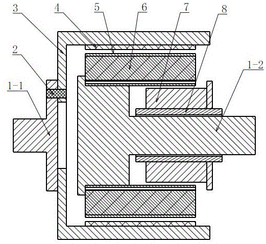
  • Figure 1
    Figure 1
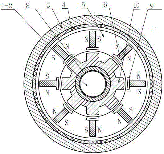
  • Figure 2
    Figure 2
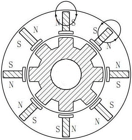
  • Figure 3
    Figure 3
Patent Text Reader

Abstract

The present invention discloses a novel permanent magnet speed regulator using a rotary salient pole to adjust magnetic flux. The novel permanent magnet speed regulator comprises a driving shaft and a driven shaft, the driving shaft is fixedly equipped with a cylindrical conductor rotor, and a permanent magnet rotor of which one end is fixed to the driven shaft is arranged in a chamber formed by the cylindrical conductor rotor. Moreover, a radial gap exists between the permanent magnet rotor and the cylindrical conductor rotor, a ratchet wheel sleeve rotating together with the driven shaft and a salient pole magnetic conductive magnet yoke capable of rotating relatively on the ratchet wheel sleeve are arranged at the lower part of the other end of the permanent magnet rotor, and a plurality of tangential permanent magnet magnetic steels are arranged in the permanent magnet rotor at equal intervals. According to the present invention, the problem that a conventional cylindrical permanent magnet speed regulator adjusts the relative positions of the permanent magnet rotor and the cylindrical conductor rotor in an axial direction to reduce the large the occupied space of an effective part of the coupling area of the permanent magnet rotor and the conductor rotor is avoided, an additional axial space is not needed, and an adjusting mechanism, such as an additional complicated cylinder is also not needed, so that the whole speed regulator is more compact and reasonable in structure, and a transmission torque under the same size is improved substantially.
Need to check novelty before this filing date? Find Prior Art

Description

technical field

[0001] The invention relates to a drive speed regulating device, in particular to a speed regulating device which utilizes electromagnetically induced eddy current for torque transmission. Background technique

[0002] In large-scale mining, petrochemical, electric power and metallurgy industries, due to the needs of energy saving and environmental protection, the application of permanent magnet speed control devices is becoming more and more widespread. The permanent magnet speed control device can adapt to various harsh environments, including places with large grid voltage fluctuations, serious harmonics, flammable, explosive, humid, dusty, etc., and can adjust the speed of the load online to meet the actual operation needs of the system and realize speed regulation Energy saving, the energy saving rate is 10%~65%.

[0003] The existing permanent magnet governor mainly includes cylindrical permanent magnet governor and disc permanent magnet governor. To ...

Examples

Embodiment Construction

[0019] The present invention will be further described below in conjunction with the accompanying drawings.

[0020] Such as figure 1 As shown, a new type of permanent magnet speed governor for adjusting magnetic flux by rotating salient poles includes a drive shaft 1-1 and a driven shaft 1-2, and the drive shaft 1-1 is fixedly provided with a cylindrical conductor rotor 3, so The cavity formed by the cylindrical conductor rotor 3 is provided with a permanent magnet rotor 5 whose end is fixed to the driven shaft 1-2, and there is a radial gap between the permanent magnet rotor 5 and the cylindrical conductor rotor 3, so The lower part of the other end of the permanent magnet rotor 5 is provided with a ratchet sleeve 8 that rotates with the driven shaft 1-2 and a salient pole magnetically conductive yoke 7 that can rotate relatively on the ratchet sleeve. A plurality of tangential permanent magnet steels 6 are arranged at intervals, and the use of tangential permanent magnet s...