Disc-shaped rotating disc permanent magnet adjustment device

A regulator, permanent magnet technology, applied in the direction of electrical components, electromechanical devices, electromechanical transmission devices, etc., can solve the problems of many fault points, short life cycle, many electrical components, etc., to achieve controllable output torque and speed, installation and debugging. Simple, effect of increasing coupling area

Active Publication Date: 2014-07-09
QINGDAO SPRING ENERGY TECH
View PDF5 Cites 0 Cited by
  • Summary
  • Abstract
  • Description
  • Claims
  • Application Information

AI Technical Summary

Problems solved by technology

Dampers and valves are traditional methods, which can effectively adjust the flow or pressure, but the disadvantages are also obvious: no energy saving, easy to cause impact in the system, and loud noise
Although the hydraulic coupling can adjust the speed and save energy to a certain extent, its efficiency is low and it is not stable enough
Inverter and internal feedback chopper speed regulation use the method of directly changing the motor speed to adjust the system and load. The efficiency is high and the energy saving effect is good. Short, with electromagnetic interference, high maintenance costs

Method used


Image

  • Disc-shaped rotating disc permanent magnet adjustment device

Examples


Embodiment 1

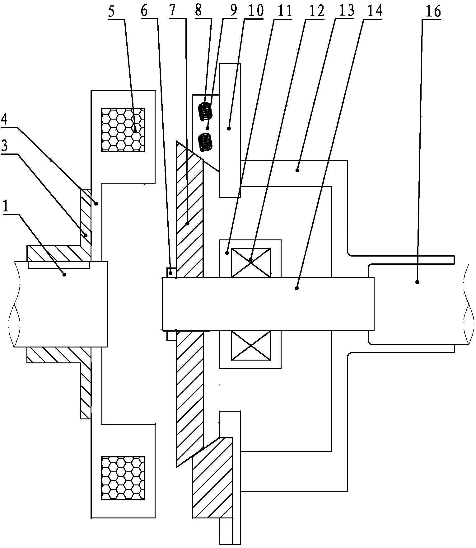
[0018] Such as figure 1 As shown, the present invention includes: a split and coaxial first shaft 1 and a second shaft 16, the first shaft 1 is covered with a permanent magnetic turntable 4 and a hub 3, and the hub 3 includes a The interference-fit cylindrical fixing part and the ring-shaped connecting part fixedly connected with the permanent magnet turntable 4 by bolts, the second shaft 16 is fitted with a shaft sleeve 13, and the shaft sleeve 13 is fitted with a conductor turntable 10 , it is characterized in that: a circle of permanent magnets 5 is installed outside the outer diameter edge of the permanent magnet turntable 4, and the magnetic pole direction of the permanent magnets 5 is perpendicular to the surface of the permanent magnet turntable 4, and different poles are installed between adjacent permanent magnets 5; the shaft There is an extension shaft 14 coaxial with the second shaft 16 in the sleeve 13, and one end of the extension shaft 14 is fixedly connected to...


PUM


Abstract

Disclosed is a disc-shaped rotating disc permanent magnet adjustment device. The disc-shaped rotating disc permanent magnet adjustment device comprises a first shaft and a second shaft, wherein the first shaft and the second shaft are arranged in a split mode and are coaxial with each other. The first shaft is sleeved with a permanent magnet rotating disc and a hub. The hub comprises a tubular fixing part in clearance fit with the first shaft and an annular connecting part fixedly connected with the permanent magnet rotating disc through a bolt. The second shaft is sleeved with a shaft sleeve, and a conductor rotating disc is installed at one end of the shaft sleeve. The disc-shaped rotating disc permanent magnet adjustment device is characterized in that a circle of permanent magnets are installed outside the outer-diameter edge of the permanent magnet rotating disc, and the magnetic pole of the permanent magnets is perpendicular to the surface of the permanent magnet rotating disc, and adjacent permanent magnets are installed in an opposite-polarity mode; an extended shaft coaxial with the second shaft is arranged in the shaft sleeve, one end of the extended shaft is fixedly connected to the shaft sleeve, and a frustum-shaped adjustment disc is installed at the other end of the extended shaft, wherein the outer diameter of the adjustment disc decreases gradually in the direction from the first shaft to the second shaft, a circle of conductor blocks are installed on the portion, corresponding to the permanent magnets on the permanent magnet rotating disc, at the outer edge of the conductor rotating disc through springs, and the surfaces, close to the second shaft, of the conductor blocks are smooth and matched with the outer surface of the adjustment disc.

Description

technical field [0001] The invention relates to the field of drive adjustment, in particular to a permanent magnet adjuster. Background technique [0002] Existing motor systems, especially centrifugal equipment systems, mainly use the following methods to regulate flow and pressure: damper baffles, valves, hydraulic couplings, frequency converters, and internal feedback chopper speed regulation. Dampers and valves are traditional methods that can effectively adjust flow or pressure, but the disadvantages are also obvious: they are not energy-saving, easily cause shocks in the system, and cause high noise. Although the hydraulic coupling can adjust the speed and save energy to a certain extent, its efficiency is low and it is not stable enough. Inverter and internal feedback chopper speed regulation use the method of directly changing the motor speed to adjust the system and load, which has high efficiency and good energy-saving effect, but because there are many electrical...

Claims


Application Information

Patent Timeline
IPC IPC(8): H02K51/00
Inventor 王荣松
Owner QINGDAO SPRING ENERGY TECH
Why Eureka
Try Eureka