Permanent magnet governor

A permanent magnet governor and permanent magnet technology, applied in the direction of electrical components, electromechanical devices, electromechanical transmission devices, etc., can solve the problems of small relative area, short life cycle, and many electrical components, and achieve controllable output torque and speed , Installation and debugging are simple, the effect of increasing the coupling area

Active Publication Date: 2017-01-04
QINGDAO SPRING ENERGY TECH
View PDF6 Cites 0 Cited by
  • Summary
  • Abstract
  • Description
  • Claims
  • Application Information

AI Technical Summary

Problems solved by technology

Although the hydraulic coupling can adjust the speed and save energy to a certain extent, its efficiency is low and it is not stable enough
Inverter and internal feedback chopper speed regulation use the method of directly changing the motor speed to adjust the system and load, which has high efficiency and good energy-saving effect, but because there are many electrical components and many fault points, it has high environmental requirements and life cycle Short, and complex harmonic interference to the environment, high maintenance and treatment costs
[0003] In this case, the permanent magnet governor is a new type of ideal choice in the field of motor speed regulation; but because the coupling surface of the ordinary flat-plate turntable permanent magnet governor is flat, the relative area is small, and the torque is small, so the axial The force is relatively large; and because the product is heavy, the quality requirements for the bearing are high and it is easy to damage

Method used


Image

  • Permanent magnet governor
  • Permanent magnet governor
  • Permanent magnet governor

Examples


Embodiment 1

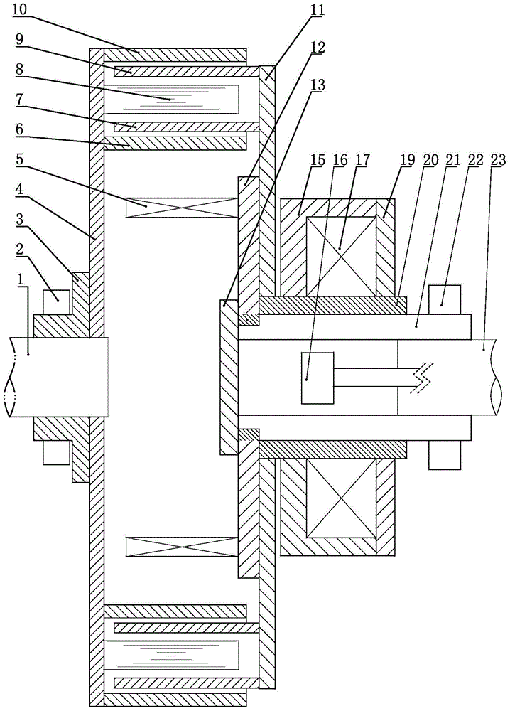
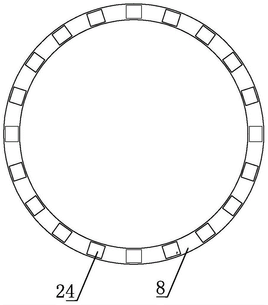
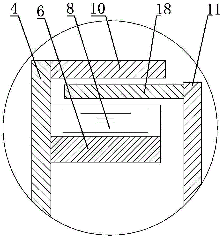
[0036] Such as figure 1 As shown, the permanent magnet governor includes: a split and coaxial first shaft 1 and a second shaft 23, the first shaft 1 is fitted with an annular permanent magnet turntable 4, and the second shaft A cylindrical shaft sleeve 21 is set on the 23, and a cylindrical inner ring sleeve 20 is sleeved on the shaft sleeve 21, and a ring-shaped conductor turntable 11 is sleeved on the inner ring sleeve 20, and the permanent magnet The outer diameter of the turntable 4 is larger than the outer diameter of the conductor turntable 11, and it is characterized in that two coaxial cylindrical protrusions are fixedly connected to the outer edge of the permanent magnet turntable 4: that is, the outer layer tube far away from the first axis 1 10 and the inner layer tube 6 close to the first shaft 1, there is a gap between the outer layer tube 10 and the inner layer tube 6, and a cylindrical non-magnetic material carrying magnet 8 is installed on the surface of the pe...

Embodiment 2

[0048] Such as Figure 3 ~ Figure 4 As shown, the present invention includes: a split and coaxial first shaft 1 and a second shaft 23, the first shaft 1 is fitted with an annular permanent magnetic turntable 4, and the second shaft 23 is fitted with A ring-shaped bushing 21, on which a cylindrical inner ring sleeve 20 is set, and a ring-shaped conductor turntable 11 is set on the inner ring sleeve 20 close to the edge of the first shaft 1, its characteristic That is: two coaxial cylindrical protrusions are formed at the outer edge of the permanent magnet turntable 4 toward the direction of the conductor turntable 11, that is, the outer layer cylinder 10 away from the first axis 1 and the inner layer cylinder 6 close to the first axis 1 , there is a gap between the outer cylinder 10 and the inner cylinder 6, the outer surface of the inner cylinder 6 or the inner surface of the outer cylinder 10 is surrounded by a ring-carrying magnet 8, and a permanent magnet is installed on th...


PUM


Abstract

The invention relates to a driving speed regulation device, in particular to a permanent-magnet speed regulator. The permanent-magnet speed regulator comprises a first shaft and a second shaft, wherein the first shaft and the second shaft are split and coaxial, the first shaft is sleeved with a circular-ring-shaped permanent-magnet rotating disk, the second shaft is sleeved with a circular-ring-shaped shaft sleeve, the shaft sleeve is sleeved with a cylindrical inner circular sleeve, and the inner circular sleeve is sleeved with a circular-ring-shaped conductor rotating disk. The permanent-magnet speed regulator is characterized in that two coaxial cylindrical protrusions are fixedly connected to the outer edge of the permanent-magnet rotating disk, and the two protrusions include an outer-layer cylinder far away from the first shaft, and an inner-layer cylinder close to the first shaft; a magnet carrier is installed between the outer-layer cylinder and the inner-layer cylinder, magnets are installed on the magnet carrier in a surrounding mode, and every two adjacent permanent magnets are installed in a heteropolar mode; the outer edge of the conductor rotating disk extends in the direction of the first shaft to form two coaxial cylindrical protrusions including an outer conductor cylinder and an inner conductor cylinder, the outer conductor cylinder extends into the position between the outer-layer cylinder and the magnet carrier, and the inner conductor cylinder extends into the position between the inner-layer cylinder and the magnet carrier.

Description

technical field [0001] The invention relates to a driving speed regulating device, in particular to a permanent magnet speed regulating device. Background technique [0002] Existing motor systems, especially centrifugal equipment systems, mainly use the following methods to regulate flow and pressure: damper baffles, valves, hydraulic couplings, frequency converters, and internal feedback chopper speed regulation. Dampers and valves are traditional methods, which can effectively adjust the flow or pressure, but the disadvantages are also obvious: they are not energy-saving, and they are easy to cause shocks in the system. Although the hydraulic coupling can adjust the speed and save energy to a certain extent, its efficiency is low and it is not stable enough. Inverter and internal feedback chopper speed regulation use the method of directly changing the motor speed to adjust the system and load, which has high efficiency and good energy-saving effect, but because there ar...

Claims


Application Information

Patent Timeline
Patent Type & Authority Patents(China)
IPC IPC(8): H02K51/00
Inventor 王荣松
Owner QINGDAO SPRING ENERGY TECH
Why Eureka
Try Eureka