
Power distribution box mounted with contact sensor
A technology of contact sensor and distribution box, which is applied to hinges with pins, substation/power distribution device shells, electrical components, etc., can solve the problems of inconvenient and reliable, and achieve reliable and stable operation, avoid shaking, and compact equipment structure Effect
- Summary
- Abstract
- Description
- Claims
- Application Information
AI Technical Summary
Problems solved by technology
Method used
Image

Examples
Embodiment Construction
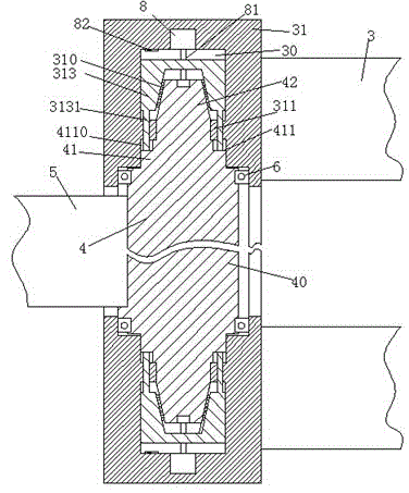
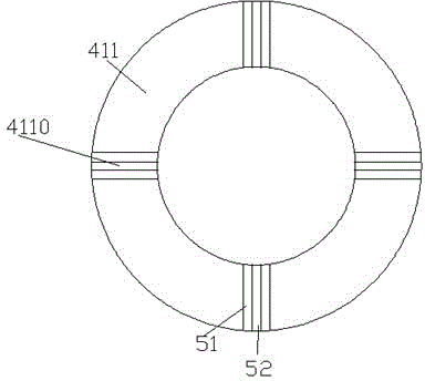
[0009] The following specific examples are combined with the attached Figure 1-2 The present invention will be described in detail.
[0010] The distribution box installed with the contact sensor according to the embodiment includes a box device for accommodating power distribution components. The hinged door 5 hinged by the bearings 31 at the upper and lower parts of the box body 3, wherein the hinged shaft 4 includes manipulation protrusions 41 arranged at the upper and lower ends, and the manipulation protrusions 41 are positioned away from the hinge. The direction of the cylindrical main body part 40 of the shaft 4 includes a shoulder part 411 and a conical part 42 in turn. The cavity 30 in the carrier 31 is provided with a positioning slider 313, and the center of the positioning slider 313 is provided with a cone. A tapered bush 310 is fixedly attached to the shaped hole to engage with the conical portion 42 and form a frictional fit, and the positioning slider 313 is ...
PUM
 Abstract
Description
Claims
Application Information