Minimalistic LED recessed light

A technology of light-emitting diodes and downlights, which is applied to semiconductor devices, light sources, and electric light sources of light-emitting elements, and can solve problems such as the inability to truly realize environmental protection and energy saving, shortened service life, and inconvenient installation

Inactive Publication Date: 2015-09-30
SKYNET ELECTRONICS
View PDF3 Cites 2 Cited by
  • Summary
  • Abstract
  • Description
  • Claims
  • Application Information

AI Technical Summary

Problems solved by technology

[0005] However, as the manufacturing cost of various high-brightness light-emitting diodes becomes cheaper, it has become a market trend to use light-emitting diodes as light-emitting elements to produce light-emitting diode downlights that meet environmental protection and energy-saving requirements. figure 2 When the structure shown is applied to the manufacture of the light emitting diode downlight, it is found that the light cup 21 of the downlight 20 is completely covered by the light emitting element 23 ( That is, the top side of the light-emitting diode (LED lamp sheet or circuit board, even, including the heat sink thereon) causes the lamp cup 21 to be unable to discharge the heat generated by the light-emitting element 23 smoothly, and the light-emitting element 23 itself The temperature is always high, and under the condition of continuous high temperature for a long time, it is very easy to cause serious material aging and light decay of the light-emitting element 23, which greatly shortens its service life
[0006] In order to improve this problem, although many companies are scrambling to design many new light-emitting diode downlight structures, most of the structures follow the basic structure of the above two downlights, and even, due to the introduction of radiators, develop a Many more complex structures not only lead to high production costs, but also make their prices unacceptable to ordinary consumers, and make the volume and weight of each LED downlight too large, causing a lot of inconvenience in installation. Finally, The commercially available LED downlights only have the false name of environmental protection and energy saving, but they cannot really achieve the purpose of environmental protection and energy saving

Method used


Image

  • Minimalistic LED recessed light
  • Minimalistic LED recessed light
  • Minimalistic LED recessed light

Examples


Embodiment Construction

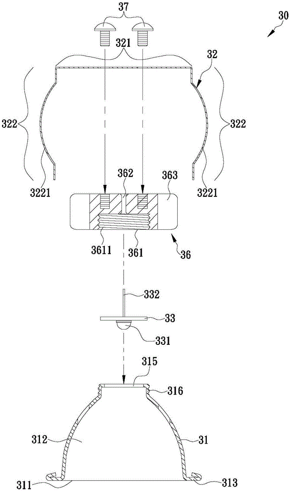
[0041] see image 3 , in the first preferred embodiment of the present invention, the extremely simplified LED downlight 30 includes a lamp cup 31, a lamp sheet 33, a heat sink 36 and an elastic support sheet 32, wherein the lamp cup 31 There is an opening 311 at the bottom of the lamp cup 31, a reflection space 312 is formed in the lamp cup 31, and a light transmission hole 315 is provided on the top of the lamp cup 31, the opening 311, the reflection space 312 and the light transmission hole 315 communicate with each other, the lamp cup 31 is adjacent to the periphery of the opening 311 and forms an annular flange 313 radially outward, the annular shape refers to a square, circular, annular wavy or other annular configuration, and the lamp cup 31 is adjacent to the light-transmitting hole 315 A first joint structure 316 is formed on the peripheral edge, and the first joint structure 316 can be an external thread or a tenon, please refer to Figure 4 , except that the outer ...


PUM


Abstract

The present invention is to provide a minimalistic LED recessed light, which includes a light cup having a bottom provided with an opening and a top provided with a light-permeable hole in communication with the opening, a light chip having a bottom surface provided with at least one LED, a heat sink having a bottom connected with the top of the light cup for positioning the light chip therebetween and allowing the LED to correspond in position to the light-permeable hole, and an elastic supporting plate fixed to a top of the heat sink and having sections respectively and symmetrically bent toward the light cup and formed with an outwardly curved engaging surface, wherein the distance between the curved engaging surfaces is greater than a diameter of a fitting hole cut in a ceiling, for effectively achieving the objects of heat dissipation and easy installation / removal of the recessed light.

Description

technical field [0001] The present invention relates to a light-emitting diode downlight, in particular to an extremely simplified light-emitting diode downlight structure composed of lamp cups, lamp sheets, radiators and elastic support sheets, so that the light-emitting diode downlight not only The structure is light, and can be easily and quickly assembled into one body, and can be easily installed in (or removed from) a mounting hole, thereby effectively realizing the effect of rapid heat dissipation. Background technique [0002] see figure 1 The shown general traditional recessed lamp 10, commonly known as a ceiling lamp, is recessed into a recessed mounting hole 141 drilled on a ceiling 14. The recessed lamp 10 includes a lamp cup 11, and the bottom of the lamp cup 11 is provided with a There is an opening 111, which is provided with an accommodating space, and the accommodating space is used for installing a light-emitting element (not shown in the figure). The sid...

Claims


Application Information

Patent Timeline
Patent Type & Authority Applications(China)
IPC IPC(8): F21S8/02F21V17/00F21V23/00F21V29/50F21Y101/02
CPCF21S8/02F21V29/70F21V7/0066F21V21/14F21Y2101/02F21K9/54F21V29/74F21K9/135F21S8/026F21V17/164F21V23/00F21V19/0055F21V21/04F21V29/773F21Y2115/10F21V21/047
Inventor 梁锦宏
Owner SKYNET ELECTRONICS
Why Eureka
Try Eureka