Laminated spiral magnetic propeller

A screw-type propeller technology, applied in propulsion systems, electrical components, electromechanical devices, etc., can solve problems such as thrust reduction, and achieve the effects of reduced energy consumption, low power consumption, and convenient processing and manufacturing

Active Publication Date: 2015-10-28
CHANGZHOU INST OF TECH
View PDF4 Cites 2 Cited by
  • Summary
  • Abstract
  • Description
  • Claims
  • Application Information

AI Technical Summary

Problems solved by technology

In this application, the magnitude of the thrust is inversely proportional to the square of the distance. When the stroke distance is long, the thrust will be significantly reduced, and it can only be applied to occasions where the propulsion distance is relatively short.

Method used


Image

  • Laminated spiral magnetic propeller
  • Laminated spiral magnetic propeller
  • Laminated spiral magnetic propeller

Examples


Embodiment

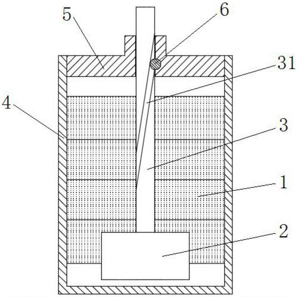
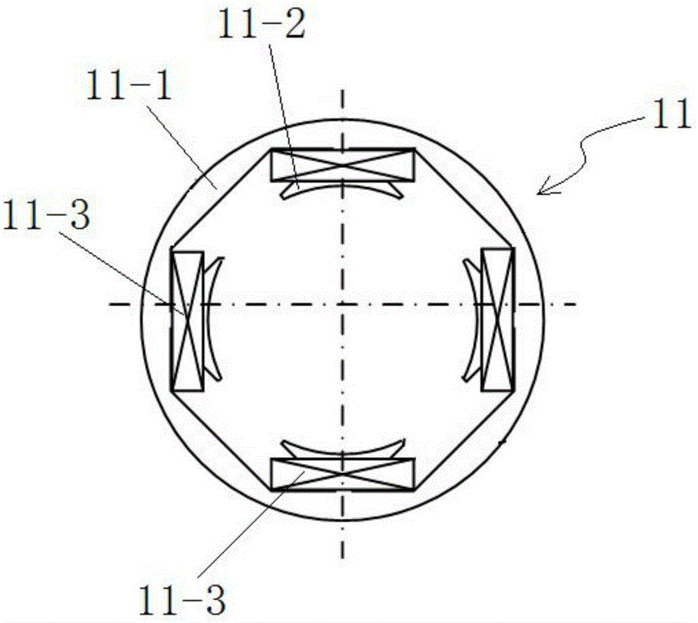
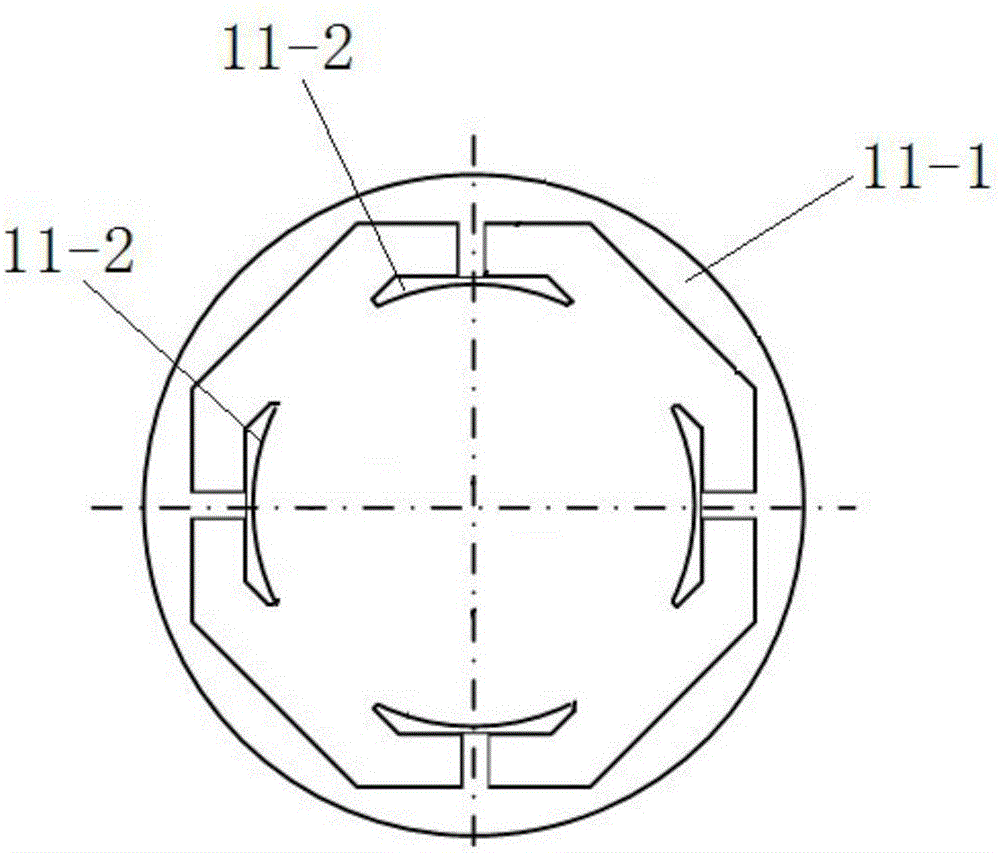
[0040] combine Figure 1 to Figure 11 As shown, taking the static magnetic pole 1 composed of 4 sets of static magnetic pole units 11 as an example, a laminated spiral magnetic thruster in this embodiment includes a casing, a static magnetic pole 1, a moving magnetic pole 2, a propulsion rod 3 and a drive circuit. The static magnetic pole 1 is composed of 4 sets of static magnetic pole units 11 laminations, and the corners of two adjacent static magnetic pole units 11 differ by an acute angle α, and the corner directions of each static magnetic pole unit 11 are all along the same direction. In this embodiment, preferably Therefore, the rotation angles of two adjacent static magnetic pole units 11 differ by an angle α=45°. The static magnetic pole unit 11 comprises a magnetic circuit ring 11-1 and a coil 11-3, and the inside of the magnetic circuit ring 11-1 is equiangularly provided with four magnetic claws 11-2 (such as image 3 shown), the inner profile of the magnetic claw...


PUM


Abstract

The present invention discloses a laminated spiral magnetic propeller, belonging to the field of electromagnetic technology. The laminated spiral magnetic propeller comprises a shell, a static magnetic pole, a moving magnetic pole, a push rod and a driving circuit. The static magnetic pole is formed by laminating a plurality of static magnetic pole units, and the rotation angle of two adjacent static magnetic pole units is an acute angle alpha. Each of the static magnetic pole units comprises four coils whose same name ends are connected. The moving magnetic pole comprises permanent magnet rings and a soft iron core. The magnetic poles of the permanent magnet rings are in S-N-S-N symmetrical distribution in a circumferential direction. The push rod is fixed to the moving magnetic pole and is provided with a spiral track which is matched with the ball of a shell sub opening part. Each of the static magnetic pole units is provided with a driving circuit which independently controls the current direction and current on and off of the coils in the static magnetic pole units. According to the laminated spiral magnetic propeller, the laminated static magnetic poles are used to orderly drive the moving magnetic pole to rotate and move up and down synchronously, the moving magnetic pole continuous propulsion is achieved, the push force is not limited by a distance, the high speed, large thrust and long distance propulsion can be realized, and the propulsion process is reversible.

Description

technical field [0001] The invention relates to a magnetic thruster, more specifically, to a laminated spiral magnetic thruster. Background technique [0002] Common propellers include pneumatic propellers and electric propellers, and electric propellers are divided into motor drive and electromagnetic drive according to the driving mode. The motor-driven thruster generally needs to be decelerated by a gear reducer to push the propulsion rod to move, so that the rotational motion of the motor can be changed into a linear motion, and the forward and reverse rotation of the motor is used to complete the push rod action. It is suitable for long-distance and slow-moving occasion. Electromagnetically driven thrusters generally use the attraction and repulsion of magnetic poles to realize the movement of the propulsion rod. Since the thrust of existing electromagnetically driven thrusters is inversely proportional to the square of the distance, the thrust will be significantly re...

Claims


Application Information

Patent Timeline
IPC IPC(8): H02K41/03
Inventor 马金祥马会全王雁平
Owner CHANGZHOU INST OF TECH
Why Eureka
Try Eureka