Array substrate, display panel, and display device

An array substrate and driving signal technology, applied in the direction of organic semiconductor devices, semiconductor devices, electrical components, etc., can solve the problems of difficulty in re-simplification, and achieve the effect of increasing the pixel aperture ratio, light and thin assembly, and large display area

Active Publication Date: 2015-11-11
BOE TECH GRP CO LTD
View PDF5 Cites 19 Cited by
  • Summary
  • Abstract
  • Description
  • Claims
  • Application Information

AI Technical Summary

Problems solved by technology

However, the current scanning circuit is very simplified, and it will be more and more difficult to simplify it. It is difficult to make further progress in realizing narrow borders with simple circuits: the design work is related to process equipment, requiring more expensive equipment and more Fine process capability, so it is difficult to further implement with stricter design rules

Method used


Image

  • Array substrate, display panel, and display device
  • Array substrate, display panel, and display device
  • Array substrate, display panel, and display device

Examples


Embodiment 1

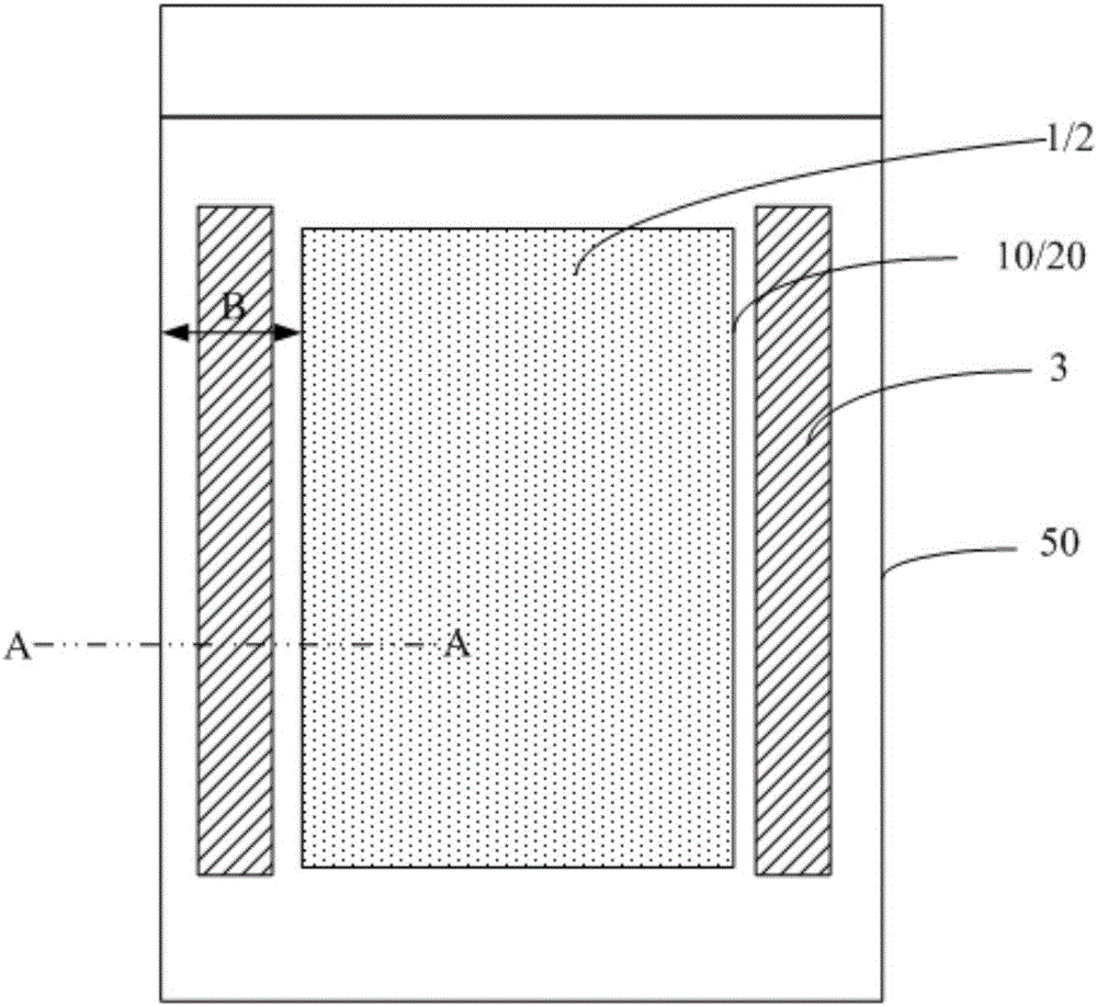
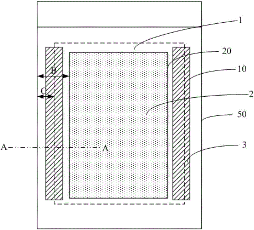
[0037] This embodiment provides an array substrate, in which the light-emitting unit extends to the GOA region, so that the light-emitting unit and the driving signal unit at least partially overlap in the orthographic projection direction, and can conveniently realize the narrow frame structure in the OLED display panel.

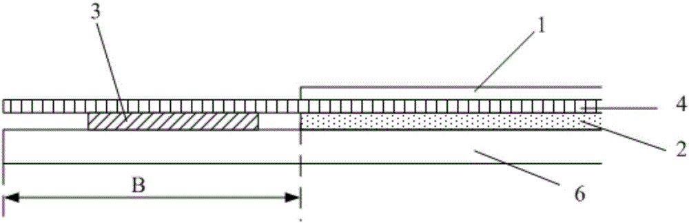
[0038] Such as image 3 As shown, the array substrate includes a light-emitting unit 1, a driving unit 2 for driving the light-emitting unit 1, and a driving signal unit 3 for providing a driving signal to the driving unit 2 (that is, a driving circuit located in the lead wiring area), and the driving unit 2 The driving signal unit 3 is disposed in the central area of ​​the array substrate, and the driving signal unit 3 is disposed in the peripheral area, and the peripheral area surrounds the central area. The light emitting unit 1 is disposed on the driving unit 2 and at least partly extends to the edge area corresponding to the driving signal unit 3 . i...

Embodiment 2

[0050] This embodiment provides a display panel, including the array substrate in Embodiment 1.

[0051] On the basis of the array substrate in Embodiment 1, a packaging substrate is formed above it, and necessary driving circuit structures are formed in the edge area (for example, for the driving circuit providing pixel data for display, mainly for data line driving), thereby forming a display panel.

[0052] Based on the structure of the above-mentioned array substrate, the display panel can provide a larger effective display area and a narrower frame width on the basis of the same outer frame size, and the assembly is lighter, thinner, and simpler.

Embodiment 3

[0054] This embodiment provides a display device, including the display panel in Embodiment 2.

[0055] The display device can be any product or component with a display function such as electronic paper, OLED panel, mobile phone, tablet computer, television, monitor, notebook computer, digital photo frame, navigator, etc.

[0056] The display device is based on the mechanism of the above-mentioned display panel, and can provide better visual experience for viewers.


PUM


Abstract

The invention belongs to the technical field of display, and specifically relates to an array substrate, a display panel, and a display device. The array substrate comprises a light emitting unit, a drive unit used to drive the light emitting unit, and a drive signal unit used to provide a drive signal for the drive unit. The drive unit is arranged in the center area of the array substrate. The drive signal unit is arranged in the boundary area surrounding the center area. The light emitting unit is arranged on the drive unit, and the light emitting unit at least partially extends to the boundary area corresponding to the drive signal unit. The array substrate can achieve the purposes of display area expansion and border width reduction, and has an effect of pixel aperture ratio increase.

Description

technical field [0001] The invention belongs to the field of display technology, and in particular relates to an array substrate, a display panel and a display device. Background technique [0002] The development direction of display technology aims to improve user experience, including the improvement of display characteristics such as color gamut, resolution PPI, and contrast. The application of the narrow frame is a way to improve user experience without improving the display effect of the display device itself. The advantage of the narrow bezel display is that the ratio of the display area to the non-display area is larger, making the display area look larger, thereby improving the user experience; at the same time, narrow bezel products are also of great benefit to the application of splicing screens, which can The width of the seam at the splicing part is reduced, and the overall display effect of the display device is improved. With the popularity of civilian displ...

Claims


Application Information

Patent Timeline
Patent Type & Authority Applications(China)
IPC IPC(8): H01L27/32
CPCH10K59/121H10K59/122H10K59/123H10K2102/3026H10K59/1213H10K59/131H01L27/1214H01L27/124
Inventor 李光殷新社孙拓
Owner BOE TECH GRP CO LTD
Why Eureka
Try Eureka