Vane pump suitable for injection molding machine

A vane pump and mechanical technology, applied in mechanical equipment, rotary piston machinery, pumps, etc., can solve the problems of impermissible vane reversal, complex structure of vane pump, impact on service life, etc., to achieve increased continuity and small frictional resistance , the effect of effective unloading

Active Publication Date: 2015-12-23
TAIZHOU HONGYI HYDRAULIC SERVO TECH CO LTD
View PDF7 Cites 4 Cited by
  • Summary
  • Abstract
  • Description
  • Claims
  • Application Information

AI Technical Summary

Problems solved by technology

[0007] At the same time, the present invention also provides a vane pump that can adapt to frequent shutdowns, allow vanes to reverse properly, reduce noise during reversal, and have a long service life; it solves the problem of vane pumps in the prior art. The pump structure is too complicated to allow the blades to reverse, the reverse noise is large, and the service life is affected by technical problems

Method used


Image

  • Vane pump suitable for injection molding machine
  • Vane pump suitable for injection molding machine
  • Vane pump suitable for injection molding machine

Examples


Embodiment

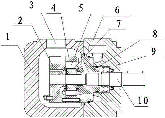
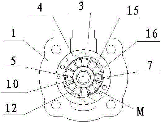
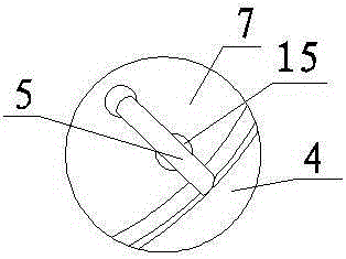
[0038] Such as figure 1 , figure 2 , image 3 As shown, a vane pump suitable for injection molding machines includes a pump body, a pump core and a transmission shaft 10 located in the pump body. The pump body includes a front housing 1 and a rear housing 9 located on the left and right sides, the front housing 1 is provided with an oil suction port 3 , and the rear housing 9 is provided with an oil pressure port 6 . The pump core includes a rotor 7 which is located on the transmission shaft 10 and rotates synchronously with the transmission shaft 10. Thirteen blade grooves 16 are provided on the rotor 7, and blades 5 are inserted in the blade grooves 16. The groove walls on the left and right sides of the blade grooves Each has a lubricating oil hole 15 on it. The lubricating oil hole 15 is a semicircular hole, and the lubricating oil hole 15 is roughly opened in the middle of the blade groove 16 , close to the outer edge of the rotor 7 .

[0039] The stator 4 is sleeved...


PUM


Abstract

The invention discloses a vane pump suitable for an injection molding machine. The vane pump comprises a pump body, a transmission shaft is arranged in the pump body, the transmission shaft is sleeved with a rotor, a stator is arranged outside the rotor, vane grooves are formed in the rotor, vanes are evenly distributed between the rotor and the stator, and the vanes are located in the vane grooves. Oil distribution discs are arranged on the two sides of the rotor, and comprise an oil suction distribution disc and an oil pressing distribution disc located on the two sides of the rotor, an oil cavity is formed among the rotor, the stator, the vanes and the oil distribution discs, and lubricating oil holes are formed in the vane grooves, and are close to one side of the oil cavity. The vane pump is simple in structure, the continuity of oil films on the surfaces of the vanes is increased, abrasion of the vanes and the vane grooves is reduced, noise is lowered, and a pump biting phenomenon is not likely to happen. The technical problems that in the prior art, a vane pump is poor in lubricating effect, the continuity of oil films formed on vanes is poor, and consequently abrasion of the vanes and vane grooves is accelerated are solved.

Description

technical field [0001] The invention relates to a vane pump, in particular to a vane pump applied to injection molding machines. Background technique [0002] As we all know, the hydraulic vane pump is the power source of the hydraulic system. It has the characteristics of low noise and high pressure, and is widely used in machine tools, plastic machines, leather machinery, forging machinery, engineering machinery and other fields. [0003] In the current patent documents, there are also many introductions about vane pumps. For example, the Chinese patent: "A vane pump (CN202441597U)", including pump body, pump cover, main shaft, pump core, oil distribution plate, fixed pump cover On the pump body, the inner cavity for the pump core and the oil distribution plate is formed between the pump body and the pump cover. Between them, one end face of the oil distribution plate is in close contact with the pump core, and a compression spring is set between the other end face of the...

Claims


Application Information

Patent Timeline
Patent Type & Authority Applications(China)
IPC IPC(8): F04C2/344F04C15/00
Inventor 齐国兴王洪继
Owner TAIZHOU HONGYI HYDRAULIC SERVO TECH CO LTD
Why Eureka
Try Eureka