Floating oil passing pipe supporting structure for integrated type hydraulic servo mechanism

A technology of hydraulic servo and support structure, applied in the direction of fluid pressure actuation device, fluid pressure actuation system components, mechanical equipment, etc., can solve the problems of seal failure, external leakage, oil leakage, etc., to improve the sealing reliability , Prevent external leakage, eliminate the effect of not easy to seal

Active Publication Date: 2015-12-23
BEIJING RES INST OF PRECISE MECHATRONICS CONTROLS +1
View PDF6 Cites 4 Cited by
  • Summary
  • Abstract
  • Description
  • Claims
  • Application Information

AI Technical Summary

Problems solved by technology

[0003] Due to the reciprocating motion of the fuel tank piston, it is necessary to reasonably design the support and sealing method of the high-pressure oil pipe inside the actuator. Otherwise, when the fuel tank piston and the fuel tank are not in the same axis, on the one hand, the reciprocating motion of the fuel tank piston will be stuck, and on the other hand On the one hand, it may cause the sealing part of the oil pipe to be subjected to mechanical external force, causing the seal to fail and cause oil leakage: external leakage, a large amount of oil leaks into the wiring cavity of the actuator, and damages electronic components; internal leakage, a large amount of oil leaks into the fuel tank, reducing The efficiency of the servo system, in severe cases, it will cause difficulty in building pressure on the servo mechanism

Method used


Image

  • Floating oil passing pipe supporting structure for integrated type hydraulic servo mechanism
  • Floating oil passing pipe supporting structure for integrated type hydraulic servo mechanism

Examples


Embodiment Construction

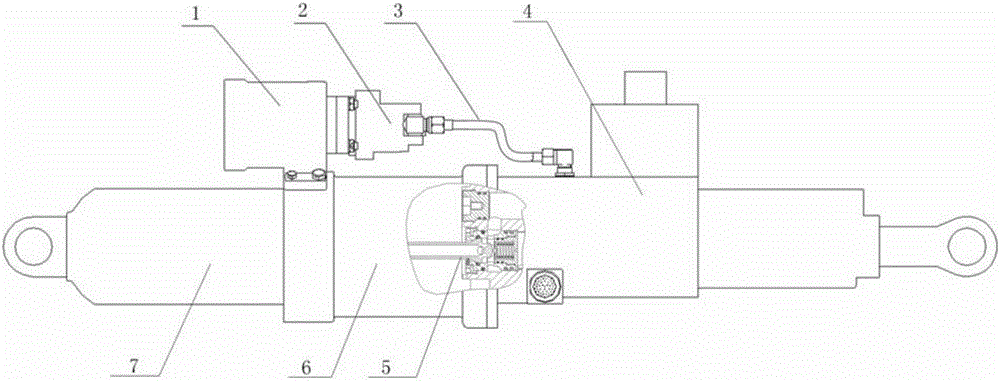
[0018] Such as figure 1 The installation layout of the integrated hydraulic servo mechanism and high-pressure floating oil pipe shown: the hydraulic servo mechanism includes a fuel tank 6, an accumulator 7, and an actuator 4, and the servo mechanism fuel tank 6 carries an electric pump, which includes an intermediate frequency motor 1 and a hydraulic pump 2. The high-pressure oil at the outlet of the hydraulic pump is introduced into the actuator 4 through the high-pressure oil pipe 3, and the high-pressure oil is directly introduced into the accumulator 7 from the actuator 4 by using the floating high-pressure oil pipe 5.

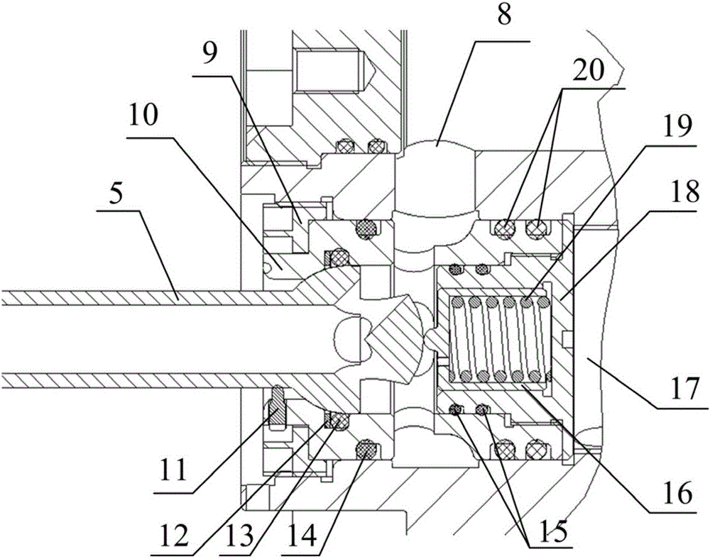
[0019] Such as figure 2 The floating oil pipe support structure for the integrated hydraulic servo mechanism shown includes an oil pipe 5, a support seat 10, a nut 9, a spring seat 18, a spring guide sleeve 16, a spring 19, a first sealing ring 13, and a second sealing ring 14 , the first double redundant structure 15 , the second double redundant struct...


PUM


Abstract

The invention discloses a floating oil passing pipe supporting structure for an integrated type hydraulic servo mechanism. The floating oil passing pipe supporting structure comprises an oil passing pipe (5), a supporting seat (10), a spring seat (18), a spring guiding sleeve (16) and a spring (19). One end of the oil passing pipe (5) is a ball head, and the supporting seat (10) is provided with a ball socket structure. The supporting seat (10) is connected with the oil passing pipe (5) through a spherical hinge so that the oil passing pipe can have certain rotating flexibility. The oil passing pipe (5) is axially supported through the spring (19). The top end of the ball head of the oil passing pipe (5) is in contact with a semispherical protruding point at one end of the spring guiding sleeve (16). The spring guiding sleeve (16) slides in a blind hole in the spring seat (18). The spring (19) is located in a blind hole of the spring guiding sleeve (16). The spring guiding sleeve (16) exerts axial force on the oil passing pipe (15) so that the ball head and the ball socket can be tightly pressed and sealed. The spring seat (18), the spring guiding sleeve (16) and the supporting seat (10) are coaxial. According to the floating oil passing pipe supporting structure, dual-redundancy sealing is adopted, and sealing is reliable.

Description

technical field [0001] The invention relates to a supporting and sealing structure, in particular to a supporting and sealing structure of a floating oil pipe for a hydraulic servo mechanism. Background technique [0002] The integrated hydraulic servo mechanism of the launch vehicle generally integrates the fuel tank, accumulator and servo actuator into one body. When the servo mechanism is working, a part of the high-pressure oil output by the hydraulic pump needs to be introduced into the accumulator oil chamber for storage to provide the peak flow required by the actuator under the action of a large signal. Although the external pipeline connection is easy to realize and easy to seal, the installation space on the arrow of the servo mechanism is narrow, and the large external installation pipeline is likely to cause interference between the engine and the servo mechanism, which is obviously not the best choice. At present, the internal high-pressure oil pipe is generall...

Claims


Application Information

Patent Timeline
Patent Type & Authority Applications(China)
IPC IPC(8): F15B21/00
Inventor 刘洪赵迎鑫陈克勤赵守军王巍
Owner BEIJING RES INST OF PRECISE MECHATRONICS CONTROLS
Why Eureka
Try Eureka