Electric type cable bending apparatus

A bending device, electric type technology, applied in the direction of cable installation device, cable installation, electrical components, etc., can solve the problem of increasing the bending workload of power cables, affecting the effect of cable bending, and damage to the outer skin of power cables, etc. Problems, to achieve the effect of increasing the scope of application, improving work efficiency and reducing labor load

Inactive Publication Date: 2016-01-20
DONGYING POWER SUPPLY COMPANY STATE GRID SHANDONG ELECTRIC POWER +2
View PDF4 Cites 9 Cited by
  • Summary
  • Abstract
  • Description
  • Claims
  • Application Information

AI Technical Summary

Problems solved by technology

In the traditional work experience, cable bending often requires the use of manual external force to bend the cable to change the path to meet the erection requirements, which increases the workload of the staff on the bending of the power cable
In the traditional bending of power cables, the operator often estimates the bending length and the radian of the curve in advance, and uses his hands and other parts of the body, or two or more people to forcefully bend the cable into a certain curvature, which is very laborious and will cause manual errors. , affecting the effect of cable bending
When the cross-section of the cable reaches 95_120mm2, the bending work must be completed by the cooperation of two or more people at the same time, and the bending time is relatively long. One end of the cable is fixed by an object and then the other end is subjected to force to complete the bending, which causes a certain degree of difficulty in the construction and maintenance of the power cable and the process is not standardized, and it is easy to cause damage to the outer skin of the power cable.

Method used


Image

  • Electric type cable bending apparatus

Examples


Embodiment Construction

[0011] The present invention will be further described in detail below in conjunction with the accompanying drawings and specific embodiments.

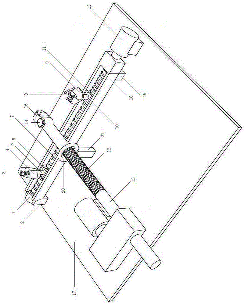
[0012] Such as figure 1 As shown, the electric cable bending device includes a chute 18, and the two ends of the chute 18 are respectively fixed on the bottom plate 17 by means of the A support leg 2 and the B support leg 19, and the A slider is slidably installed in the chute 18. 6 and B slider 11, A long rod 5 is fixed on the upper end of A slider 6, A ring 4 is rotated and installed on A long rod 5, and A bolt 3 is connected between the two protruding fronts on the upper part of A ring 4 , the B long rod 10 is fixed on the upper end of the B slider 11, the B ring 9 is rotated and installed on the B long rod 10, and the B bolt 8 is connected between the two protruding fronts of the upper part of the B ring 9, and the A ring 4 There is an electric push rod 15 in the horizontal plane where the B ring 9 is located, and the electric pu...


PUM


Abstract

The present invention discloses an electric type cable bending apparatus, and relates to the technical field of electric power transmission equipment. The electric type cable bending apparatus comprises a sliding chute, wherein two ends of the sliding chute are fixed to a bottom plate respectively through an A supporting leg and a B supporting leg, an A slide block and a B slide block are slidably arranged in the sliding chute, the upper end face of the A slide block is fixedly provided with an A long rod, an A hold ring is rotatably arranged on the A long rod, an A bolt is connected between two protruded front edges of the upper portion of the A hold ring, the upper end face of the B slide block is fixedly provided with a B long rod, a B hold ring is rotatably arranged on the B long rod, a B bolt is connected between two protruded front edges of the upper portion of the B hold ring, an electric push rod is arranged in a horizontal plane where the A hold ring and the B hold ring locate, the electric push rod is arranged on the bottom plate and perpendicular to the sliding chute; the front end of the electric push rod is fixedly provided with a hold hoop. The electric type cable bending apparatus of the present invention has the beneficial effects of good adaptability, convenient use, standard operation, labor saving and time saving, etc.

Description

technical field [0001] The present invention relates to the technical field of power transmission equipment. Background technique [0002] Electricity is an indispensable part of people's life, production, travel, etc. In recent years, the country has vigorously developed and improved infrastructure equipment, and the power transmission system has also been greatly developed and improved. With the continuous pace of electrification construction in various regions of our country With the advancement of power supply enterprises and power customers, the requirements for the design, construction and maintenance of power facilities are getting higher and higher, the awareness of safe power supply and use is gradually increasing, and the use of power cables has gradually become popular. With the gradual increase in the electricity load of power customers, and the safety, reliability and practicability of power cables are gradually recognized by customers, the use of large power ca...

Claims


Application Information

Patent Timeline
Patent Type & Authority Applications(China)
IPC IPC(8): H02G1/00B21F1/00
Inventor 吴斌李志强田彩红武金胜薛华薄如忠
Owner DONGYING POWER SUPPLY COMPANY STATE GRID SHANDONG ELECTRIC POWER
Why Eureka
Try Eureka