Supercharge Your Innovation With Domain-Expert AI Agents!

An automatic stamping machine for engineering drawings

A technology of automatic stamping machine and engineering drawings, applied in printing, stamping and other directions, which can solve the problems of heavy engineering-related responsibilities, low efficiency, and large amount of engineering drawings.

Inactive Publication Date: 2018-01-09
彭功勋
View PDF6 Cites 0 Cited by
  • Summary
  • Abstract
  • Description
  • Claims
  • Application Information

AI Technical Summary

Problems solved by technology

[0003] 1. The stamps must be consistent with the qualifications. Different professional categories and different stages have different stamps
[0004] 2. Due to the heavy responsibilities related to the project, and the design personnel at each stage have lifelong responsibilities for the project, they are very cautious about the stamped engineering drawings, which need to be bound first. The seal can only be affixed after the confirmation signature, and it is generally required to be affixed page by page
[0005] 3. Engineering drawings are generally large and urgent
[0007] 5. The thickness of engineering drawing sheets varies greatly, generally between 5mm and 50mm, and very few even exceed 50mm
[0009] At present, all units are stamped manually, which not only wastes manpower and is inefficient, but also many joints such as shoulders and elbows are damaged by long-term stamping, which is prone to occupational diseases
[0010] The existing automatic stamping machine and related stamping machine patents are all aimed at unbound documents or drawings, and do not take into account the specifications and characteristics of stamping engineering drawings, and cannot meet the requirements of automatic stamping of engineering drawings

Method used


Image

  • An automatic stamping machine for engineering drawings
  • An automatic stamping machine for engineering drawings
  • An automatic stamping machine for engineering drawings

Examples


Embodiment Construction

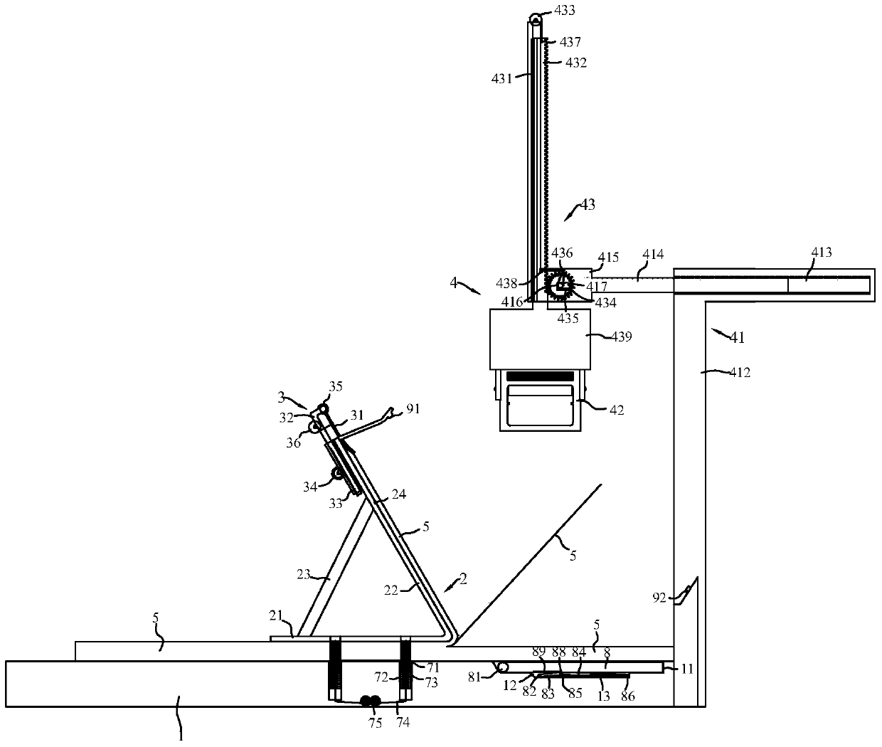
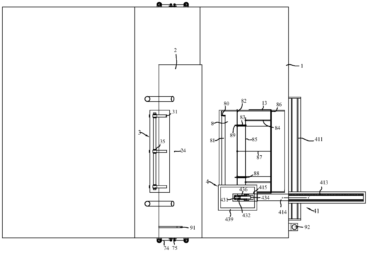
[0028] refer to Figure 1 to Figure 5 , which shows the specific structure of the preferred embodiment of the present invention. The structural features of each element of the present invention will be described in detail below, and if there is a description of the direction (up, down, left, right, front and back), it is based on figure 1 The shown structure is a reference description, but the actual use direction of the present invention is not limited thereto.

[0029] refer to Figure 1-Figure 3, the present invention provides an automatic stamping machine for engineering drawings, including a working platform 1, a splint 2, a page turner 3 and a stamping device 4, the size of the working platform 1 is designed according to the size of the A1 drawing, and can be designed according to the needs , work platform 1 adds table legs and makes table platform shape separately, also can be equipped with some fixing clips and be fixed on existing table, platform. The supporting c...


PUM


Abstract

The invention discloses an automatic stamping machine for engineering drawings, which includes a working platform, a supporting splint, a page turner and a stamping device. The supporting splint includes a drawing splint and a drawing supporting plate inclined to the drawing splint. On the above-mentioned drawing pallet, the page turner can release and fold the drawings on the outside of the drawing pallet page by page. The stamping device includes a positioning bracket, a stamping device and a stamping device which is arranged on the positioning bracket and can drive the stamping device to move up and down to complete the stamping. The stamping mechanism of the stamp action. When in use, the drawing is fixed by the splint, and then the part of the drawing on the right side of the splint is folded onto the drawing support, and the page turner is pressed down on the drawing support. When stamping is required, the page turner is released page by page. The drawing is folded on the outside of the drawing pallet, and the stamping mechanism drives the stamper to move up and down to complete the stamping action. The invention can perform page-turning and page-turning for drawings with different thicknesses, sizes and specifications, bound into books, assists the page-turning operation, replaces manual operation, and improves the efficiency of page-turning and stamping.

Description

technical field [0001] The invention is used in the technical field of sealing engineering drawings, and in particular relates to an automatic sealing machine for engineering drawings. Background technique [0002] Units such as design institutes or construction drawing review centers have a large number of engineering drawings to be stamped. The affixing of engineering stamps has its special features, mainly including: [0003] 1. The stamps must be consistent with the qualifications, and the stamps are different for different professional categories and stages. [0004] 2. Due to the heavy responsibilities related to the project, and the design personnel at each stage have lifelong responsibilities for the project, they are very cautious about the stamped engineering drawings. The seal can only be affixed after the confirmation signature, and it is generally required to be affixed page by page. [0005] 3. Engineering drawings are generally large and urgent. Some proje...

Claims


Application Information

Patent Timeline
Patent Type & Authority Patents(China)
IPC IPC(8): B41K3/02B41K3/50B41K3/62
Inventor 彭功勋
Owner 彭功勋
Features
  • R&D
  • Intellectual Property
  • Life Sciences
  • Materials
  • Tech Scout
  • Unparalleled Data Quality
  • Higher Quality Content
  • 60% Fewer Hallucinations
Learn More