
Intelligent lithium battery charger
A lithium battery and charger technology, applied in different battery charging, battery circuit devices, current collectors, etc., can solve problems such as inconvenience and waste of use
- Summary
- Abstract
- Description
- Claims
- Application Information
AI Technical Summary
Problems solved by technology
Method used
Image

Examples
Embodiment approach
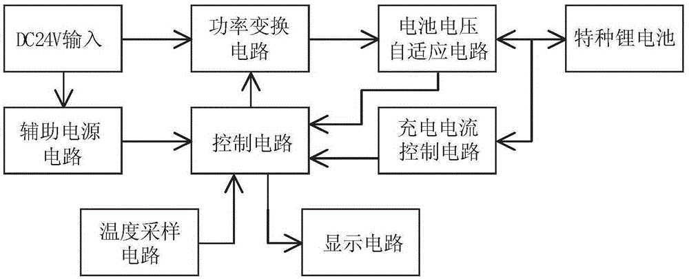
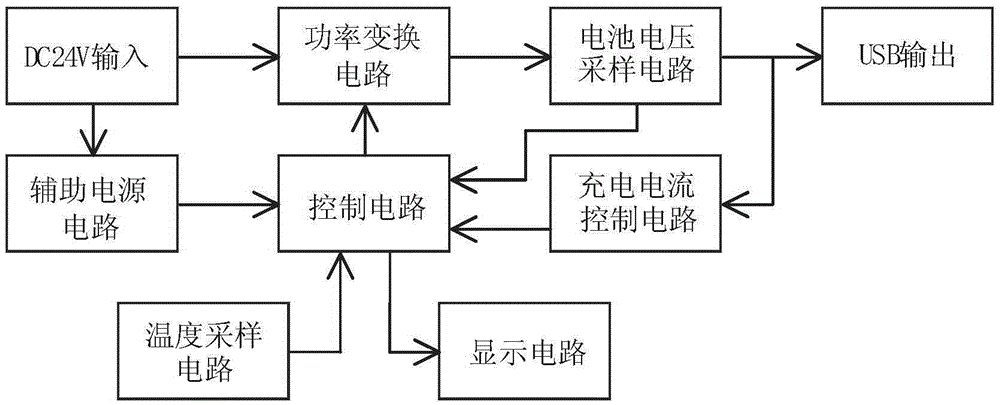
[0050] Figure 11 For the schematic diagram of the control circuit, the circuit is mainly composed of a piece of MCU. By sampling signals such as voltage, current and temperature, the feedback circuit of the power conversion circuit is intervened to make it output the predetermined charging voltage and charging current, and through the charging current signal Determine whether the battery is fully charged and send a signal to the indicator light for display.
[0051] Implementation of temperature sampling circuit
[0052] Figure 12 It is the schematic diagram of the temperature sampling circuit, and V1 in the figure is a temperature / voltage converter, which can convert the ambient temperature into a voltage signal and send it to the A / D sampling terminal of the MCU.
PUM
 Abstract
Description
Claims
Application Information