Three-dimensional printing apparatus

A technology of 3D printing and equipment, applied in the field of 3D printing, can solve problems such as limited printing speed, achieve the effect of improving printing efficiency, high quality, and eliminating delamination

Active Publication Date: 2016-03-23
湖州烁众精密智造有限公司
View PDF10 Cites 12 Cited by
  • Summary
  • Abstract
  • Description
  • Claims
  • Application Information

AI Technical Summary

Problems solved by technology

When the 3D printing equipment prints the product, it is printed in layers. After printing a layer, the discharge print head moves up the distance of one layer, and then adjusts the position in translation, and then prints again. In this way, wait for the discharge print head to go up first. It will take a long time to move and move again, which will limit the printing speed

Method used


Image

  • Three-dimensional printing apparatus
  • Three-dimensional printing apparatus
  • Three-dimensional printing apparatus

Examples


Embodiment 1

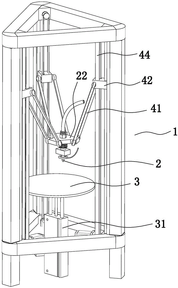
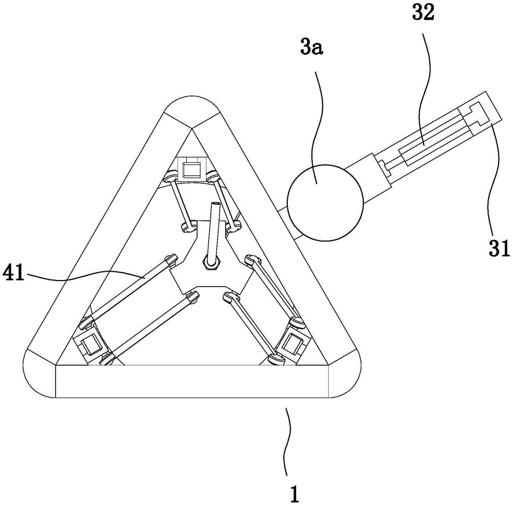
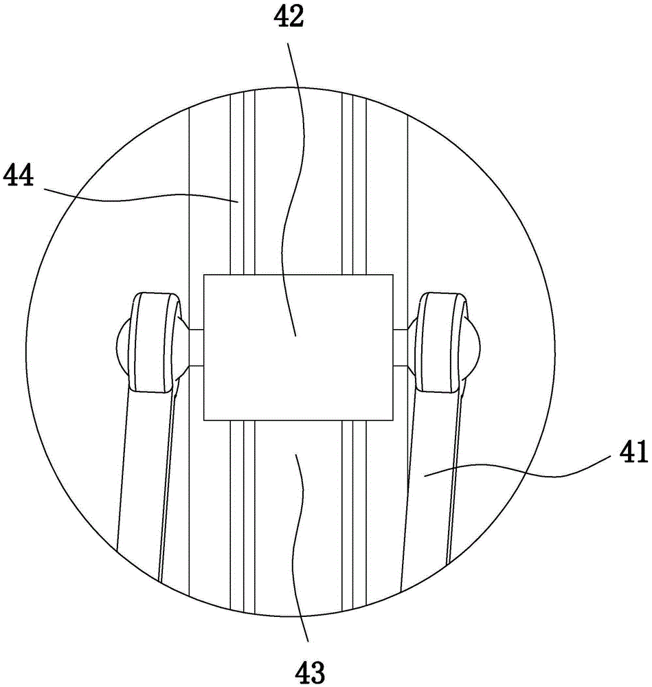
[0030] Embodiment 1: as Figure 1 to Figure 6 In the illustrated embodiment, a three-dimensional printing device includes a main frame 1, a discharge print head 2, a forming printing platen 3 inside the main frame, and a device for driving the discharge print head to move so as to change the output A print head displacement adjustment mechanism for the position of the material print head, the discharge print head is provided with a print head feed end for inputting printing materials, and the discharge print head is provided with a discharge port connected to the print head feed end. Passage 21, a platen adjustment cylinder 31 is provided below the forming and printing platen. The platen adjustment cylinder includes a cylinder body, a piston that slides with the cylinder body, and a piston rod connected to the piston. The piston rod of the platen adjustment cylinder is on the top 1. The cylinder body is at the bottom, the piston rod of the platen adjustment cylinder is vertica...

Embodiment 2

[0036] Embodiment 2: the basic structure and implementation mode of this embodiment are the same as embodiment 1, and its difference is:

[0037] like Figure 7 As shown in , the discharge channel is provided with a thermal insulation tube 23 coaxial with the discharge channel. The upper and lower ends of the thermal insulation tube are open. Thin material coloring channel 24 is formed between the wall and the channel wall of the discharge channel (that is, the inner wall of the discharge print head). The outlet of the coloring tube faces the outer wall of the heat-insulating tube, and a coloring check valve 521 is arranged at the outlet of the coloring tube. The passing direction of the coloring one-way valve is from the coloring pipe to the discharge channel, the highest point of the coloring port is lower than the highest point of the heat insulation cylinder, and the lowest point of the coloring port is higher than the lowest point of the heat insulation cylinder. The ver...

Embodiment 3

[0038] Embodiment 3: the basic structure and implementation mode of this embodiment are the same as embodiment 1 or 2, and its difference is:

[0039] like Figure 8 , Figure 9 As shown in , the feed end of the printing head is connected to the mixing discharge end of a mixing cylinder 6 through a feed pump, and the mixing cylinder is provided with a cylinder feed port, and also includes several feeding ports for feeding the cylinder feed port. A raw material cylinder, a melting heater is provided in the raw material cylinder, a discharge valve is provided at the mixing discharge end, a mixing shaft 61a driven by a mixing motor 61 is arranged in the mixing cylinder, and a plurality of stirring blades 61b are arranged on the mixing shaft . The mixing motor is arranged above the mixing cylinder, the output end of the mixing motor is connected to the input end of a mixing speed reducer 61c, and the output end of the mixing speed reducer extends into the mixing cylinder and is ...


PUM


Abstract

The invention discloses a three-dimensional printing apparatus. The three-dimensional printing apparatus comprises a main frame, a discharge printing head and a forming printing bedplate located within the main frame, and further comprises a printing head displacement adjusting mechanism for driving the discharge printing head to move so as to change the position of the discharge printing head; the discharge printing head is provided with a printing head feed end for inputting printing raw materials; a discharge channel communicating with the printing head feed end is arranged in the discharge printing head; a bedplate adjusting cylinder is arranged blow the forming printing bedplate, and comprises a cylinder block, a piston in sliding fit with the cylinder block, and a piston rod connected with the piston; the piston rod of the bedplate adjusting cylinder is above the cylinder block; moreover, the piston rod of the bedplate adjusting cylinder is vertical and the upper end of the piston rod is connected to a bottom surface of the forming printing bedplate. The three-dimensional printing apparatus has the beneficial effects as follows: the structure is reasonable and a large degree of freedom of adjustment is achieved; simultaneously adjustment of relative heights and positions of the discharge printing head can be effectively realized, and a comprehensive adjusting speed and printing efficiency can be improved substantially.

Description

technical field [0001] The invention belongs to the technical field of 3D printing, and in particular relates to a three-dimensional printing device. Background technique [0002] 3D printer, also known as three-dimensional printer (3DP), is a machine that uses cumulative manufacturing technology, that is, rapid prototyping technology. 3D printing technology is a digital model file-based technology that uses bondable materials such as molten plastic to manufacture three-dimensional objects by printing layers of adhesive materials, that is, the technology of constructing objects by layer-by-layer printing. At this stage, 3D printers are mostly used to manufacture products. [0003] The 3D printer mainly includes a printing structure (print head), a forming printing platen (on which the product is formed), and a printing head displacement adjustment mechanism (which can change the position of the printing head in space, so that the printed raw materials can fall on the formin...

Claims


Application Information

Patent Timeline
IPC IPC(8): B29C67/00B33Y30/00
Inventor 王正波许启明王舒文陈智浩唐乔
Owner 湖州烁众精密智造有限公司
Why Eureka
Try Eureka