Transformer oil temperature detection system

A technology of transformer oil and detection system, which is applied in transformer/inductor cooling, thermometer, transformer/inductor components, etc., can solve the problems of inability to meet detection requirements, transformer insulation hazards, transformer short circuit, etc. Convenient and accurate detection

Inactive Publication Date: 2016-03-30
STATE GRID JIANGSU ELECTRIC POWER CO ELECTRIC POWER RES INST +1
View PDF8 Cites 6 Cited by
  • Summary
  • Abstract
  • Description
  • Claims
  • Application Information

AI Technical Summary

Problems solved by technology

[0002] In the current power system, oil-immersed transformers often encounter high temperature or high humidity in the actual use environment. In this case, the transformer oil will heat up and decompose other substances from the oil. Some substances will damage the insulation of the transformer. It will cause considerable harm and seriously cause the internal short circuit of the transformer or even an explosion.
The current detection method is to heat the transformer oil separately, and then detect the impurity components in it. This method only detects the influence of the heating body on the oil when it is heated, and there are differences in the time and temperature of the impurities produced by the actual transformer with iron core and coil. , unable to meet the actual detection needs

Method used


Image

  • Transformer oil temperature detection system
  • Transformer oil temperature detection system
  • Transformer oil temperature detection system

Examples


Embodiment 1

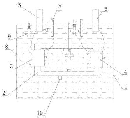
[0016] Such as figure 1 As shown, the transformer oil temperature detection system includes an oil tank 1 with an iron core 2 inside. A high-voltage coil 3 and a low-voltage coil 4 are wound on the iron core 2. The upper part of the high-voltage coil 3 is connected to the high-voltage insulating bushing 5 on the oil tank 1. 4 is connected to the low-voltage insulating bushing 6 on the oil tank 1, and the upper part of the oil tank 1 is also equipped with a tap switch 7 for adjusting the number of coil turns. The oil tank 1 is filled with transformer oil 8; the oil tank 1 is equipped with a plurality of ceramic heating plates 9 The iron core 2, the high-voltage coil 3, and the low-voltage coil 4 are wound with a plurality of thermal radiation optical fiber sensors 10, and the thermal radiation optical fiber sensors 10 are respectively arranged on the upper, middle and lower parts of the iron core 2, the high-voltage coil 3, and the low-voltage coil 4, and the thermal radiation o...


PUM

PropertyMeasurementUnit
lengthaaaaaaaaaa

Abstract

The invention discloses a transformer oil temperature detection system, and the system comprises an oil tank. An iron core is provided with a high-voltage coil and a low-voltage coil in a winding manner. The upper part of the high-voltage coil is connected with a high-voltage insulating bush on the oil tank, and the low-voltage coil is connected with a low-voltage insulating bush on the oil tank. The upper part of the oil tank is also provided with a tapping switch which is used for adjusting the number of turns per coil. The oil tank contains transformer oil. The interior of the oil tank is provided with a plurality of ceramic heating pieces, and the iron core, the high-voltage coil and the low-voltage coil are provided with a plurality of thermal radiation optical fiber sensors in a winding manner. The thermal radiation optical fiber sensors are respectively disposed at the upper, central and lower parts of the iron core, the high-voltage coil and the low-voltage coil, wherein the number of the thermal radiation optical fiber sensors is 2-4. The ceramic heating pieces are cross-shaped, and the interior of each ceramic heating piece is provided with a heating core, wherein the heating cores are connected with electrodes. The exteriors of the heating cores are provided with ceramic layers, and the upper parts of the heating cores are provided with a plurality of core heads which are embedded into the ceramic layers. The beneficial effects of the invention are that the system is simple in structure, is convenient to use, is accurate in detection, truly detects the changes of oil of an oil immersed transformer in actual operation.

Description

technical field [0001] The invention belongs to the technical field of an analog transformer overheating fault monitoring device, and in particular relates to a transformer oil temperature detection system. Background technique [0002] In the current power system, oil-immersed transformers often encounter high temperature or high humidity in the actual use environment. In this case, the transformer oil will heat up and decompose other substances from the oil. Some substances will damage the insulation of the transformer. It will cause considerable harm and seriously cause the internal short circuit of the transformer or even an explosion. The current detection method is to heat the transformer oil separately, and then detect the impurity components in it. This method only detects the influence of the heating body on the oil when it is heated, and there are differences in the time and temperature of the impurities produced by the actual transformer with iron core and coil. ...

Claims


Application Information

Patent Timeline
Patent Type & Authority Applications(China)
IPC IPC(8): G01K11/32H01F27/14H01F27/40
CPCH01F27/402G01K11/32
Inventor 陶风波周志成李建生贾金书毕海成
Owner STATE GRID JIANGSU ELECTRIC POWER CO ELECTRIC POWER RES INST
Why Eureka
Try Eureka