Rotary transformer

A rotary transformer and rotor technology, applied in the direction of transformers, transformer/inductor magnetic cores, transformer/inductor components, etc., can solve problems such as large insertion loss, signal distortion, unfavorable broadband signal transmission, etc., to reduce reluctance, The effect of reducing loss

Active Publication Date: 2016-05-18
DONGGUAN MENTECH OPTICAL & MAGNETIC CO LTD
View PDF5 Cites 3 Cited by
  • Summary
  • Abstract
  • Description
  • Claims
  • Application Information

AI Technical Summary

Problems solved by technology

[0003] The insertion loss of the resolver generally increases as the frequency of the electromagnetic field increases. The existing resolver is not conducive to the transmission of broadband signals, because when it works in a high-frequency magnetic field, the frequency is 100MHz or even higher. In the electromagnetic field of high frequency, the insertion loss will be particularly large, so that the signal in the high frequency part has been seriously distorted

Method used


Image

  • Rotary transformer
  • Rotary transformer
  • Rotary transformer

Examples


Embodiment Construction

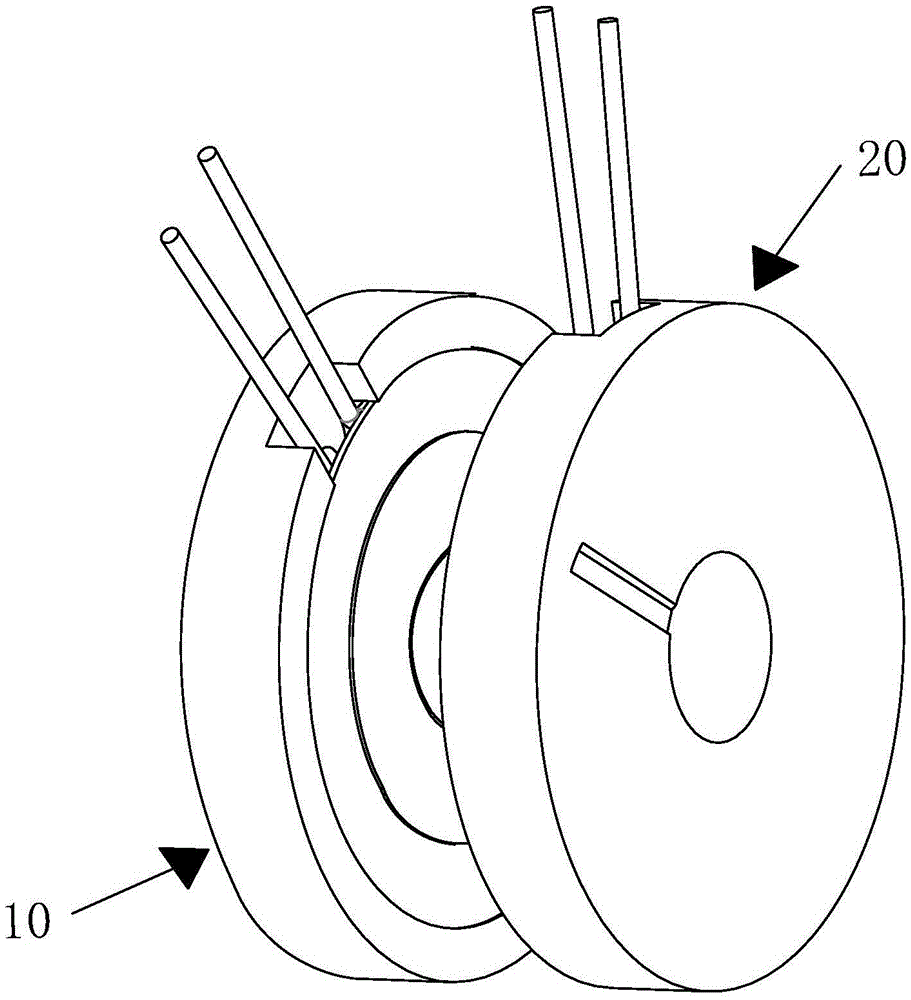
[0042] An embodiment of the present invention provides a rotary transformer for realizing broadband signal transmission.

[0043] In order to make the purpose, features and advantages of the present invention more obvious and understandable, the technical solutions in the embodiments of the present invention will be clearly and completely described below in conjunction with the accompanying drawings in the embodiments of the present invention. Obviously, the following The described embodiments are only some, not all, embodiments of the present invention. Based on the embodiments of the present invention, all other embodiments obtained by persons of ordinary skill in the art without making creative efforts belong to the protection scope of the present invention.

[0044] The technical solutions of the present invention will be further described below in conjunction with the accompanying drawings and through specific implementation methods.

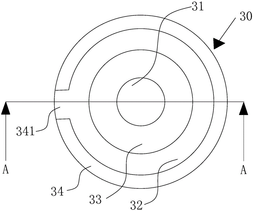
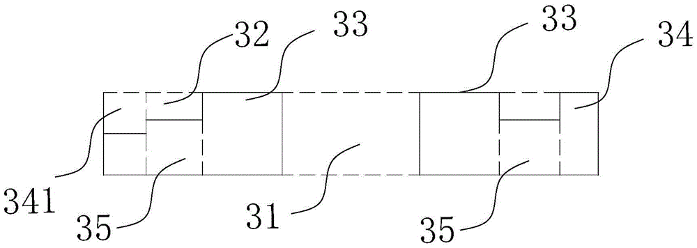
[0045] Please refer to figure 1 , ...


PUM

PropertyMeasurementUnit
widthaaaaaaaaaa
diameteraaaaaaaaaa
heightaaaaaaaaaa

Abstract

The invention discloses a rotary transformer which is used for achieving transmission of broadband signals. The rotary transformer comprises a stator and a rotor, the rotor and the stator are not in physical contact, magnetic cores of the same structure are adopted for the rotor and the stator, each magnetic core comprises a first magnetizer, a second magnetizer and a third magnetizer, the first magnetizers, the second magnetizers and the third magnetizers form magnetic circuits of the magnetic cores, and the areas of all magnetic flux surfaces on the magnetic circuits are the same. According to the rotary transformer, by optimizing the structures of the magnetic cores, the areas of all cross sections on the magnetic circuits of the magnetic cores are the same or approximately the same so as to lower magnetic resistance, so that the loss in high-frequency signal transmission is lowered, and broadband signals wider in frequency range can be transmitted under the situation that it is guaranteed that signals are distortionless.

Description

technical field [0001] The invention relates to the field of transformers, in particular to a rotary transformer. Background technique [0002] When a resolver is used in a circuit, there will be a certain insertion loss more or less, and the insertion loss can be expressed in decibels, which is the most common measurement technical index for resolver performance. Generally speaking, in the same magnetic field, the smaller the insertion loss of the resolver, the better the performance of the resolver. [0003] The insertion loss of the resolver generally increases as the frequency of the electromagnetic field increases. The existing resolver is not conducive to the transmission of broadband signals, because when it works in a high-frequency magnetic field, the frequency is 100MHz or even higher. In the electromagnetic field of high frequency, the insertion loss will be particularly large, so that the signal in the high frequency part has been seriously distorted. Contents...

Claims


Application Information

Patent Timeline
Patent Type & Authority Applications(China)
IPC IPC(8): H01F38/18H01F27/24H01F27/30
CPCH01F27/24H01F27/306H01F38/18
Inventor 马宗俊黄家毅
Owner DONGGUAN MENTECH OPTICAL & MAGNETIC CO LTD
Why Eureka
Try Eureka