Remote debug system for projector

A remote debugging and projector technology, applied in the field of remote control, can solve problems such as low efficiency and inconvenient remote debugging, and achieve the effect of avoiding input, improving accuracy, efficiency and service efficiency

Inactive Publication Date: 2016-05-25
成都创屹远景科技有限公司
View PDF4 Cites 1 Cited by
  • Summary
  • Abstract
  • Description
  • Claims
  • Application Information

AI Technical Summary

Problems solved by technology

[0004] In order to overcome the inconvenience and low efficiency of remote debugging of existing projectors and improve the debugging and service efficiency of engineers, the present invention provides a remote debugging system for projectors, including:

Method used


Image

  • Remote debug system for projector

Examples


Embodiment Construction

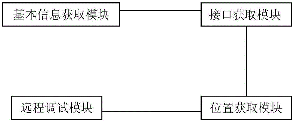
[0037] Such as figure 1 As shown, the remote debugging system for a projector includes a basic information acquisition module, an interface acquisition module, a location acquisition module and a remote debugging module, wherein:

[0038] The basic information acquisition module is used to acquire the brand and model information of the projector; according to a preferred embodiment of the present invention, the brand and model information can be acquired by scanning the two-dimensional code of the projector. According to other embodiments of the present invention, the brand and model information can also be obtained by directly checking the nameplate or trademark of the projector.

[0039] The interface obtaining module is used to obtain the remote debugging database interface and the graphic image proxy interface of the projector server according to the brand and model information. According to a preferred embodiment of the present invention, the remote debugging database in...


PUM


Abstract

In order to solve the problems of inconvenient remote debug and low efficiency of an existing projector and improve the debug and service efficiency of engineers, the invention provides a remote debug system for a projector. The system comprises a basic information acquisition module, an interface acquisition module, a position acquisition module and a remote debug module. According to the system, an engineer can conveniently and remotely know the working condition of the projector in an environment leaving from a server, and the input of a complicated instruction is avoided in the manner of an identifier, so that the debug accuracy and efficiency are improved and the service efficiency is improved.

Description

technical field [0001] The present invention relates to the technical field of remote control, and more specifically, to a remote debugging system for a projector. Background technique [0002] If there is a problem with the existing projector, you usually hope that the after-sales engineer will debug it on site, including software and hardware damage, you need to go to a dedicated customer service to solve it. On-site technicians will determine whether it is a software problem or a hardware problem through software testing or instrument debugging. problems, and follow-up analysis and resolution. For example, if a fault is found, the traditional processing flow of "user phone call for repair→engineer appointment→engineer's on-site processing" is usually adopted, which often takes days or even weeks, and every time the after-sales engineer comes to the door will cost the manufacturer a lot of money service fee. However, the actual situation is that a large part of the fault...

Claims


Application Information

Patent Timeline
IPC IPC(8): G06F11/22
CPCG06F11/2294
Inventor 刘颖
Owner 成都创屹远景科技有限公司
Why Eureka
Try Eureka