Novel profile pulling method

A profile, a new type of technology, applied in the field of metal processing, can solve the problems of poor versatility, poor flexibility, high equipment manufacturing costs, etc., to achieve efficient and stable traction effects, expand the traction work space, and move and walk flexibly

Active Publication Date: 2016-06-15
广东省智行机器人科技有限公司
View PDF5 Cites 6 Cited by
  • Summary
  • Abstract
  • Description
  • Claims
  • Application Information

AI Technical Summary

Problems solved by technology

[0005] 1. The complex structure of the existing traction equipment that implements the traction method and the horizontal placement on the ground lead to a large occupation area, resulting in high equipment manufacturing costs and increased production costs of profiles
At the same time, the horizontal structure of the traction equipment is also easily affected by the ground conditions, making it difficult to ensure the straightness and straightness of the mechanical arm walking
[0006] 2. The existing profile traction method only uses a trolley with a clamping arm moving along a straight line to pull the profile, resulting in low production efficiency
[0007] 3. In the existing profile pulling method, the clamps for clamping profiles are poor in versatility
Due to the inconsistent sizes and specifications of the produced profiles, the fixture can only be used for clamping profiles with one diameter specification. For metal profiles of different sizes, the fixture needs to be replaced, resulting in poor versatility, poor clamping effect and high cost.
[0008] 4. Most of the existing profile traction methods use a traction trolley with a clamp to realize the traction of the profile. The simple combination of the clamp and the walking trolley has poor flexibility and can only realize the functions of walking and clamping

Method used


Image

  • Novel profile pulling method
  • Novel profile pulling method
  • Novel profile pulling method

Examples


Embodiment 1

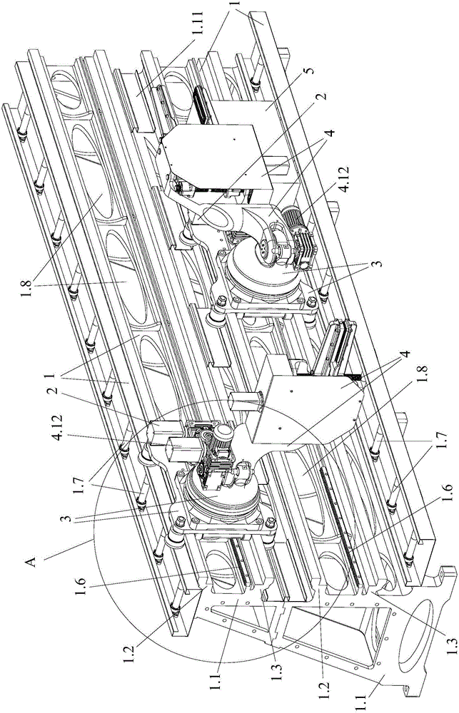
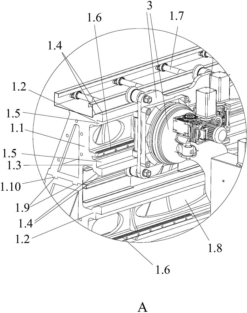
[0045] In this embodiment, the following description will be made by taking the profile traction method using a vertical profile double-track traction robot as an example.

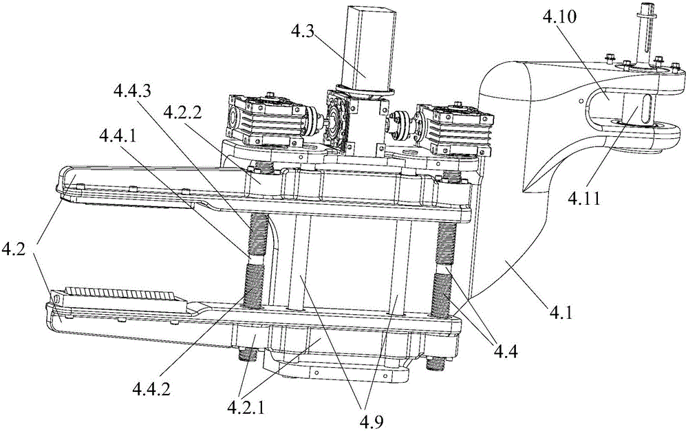
[0046] Such as Figures 1 to 7 As shown, the vertical profile double-track pulling robot of the present invention is used to pull the profile at the discharge port. The traction robot includes a control mechanism 5 and two traction units, wherein each traction unit includes a vertical walking track 1, a mechanical arm for clamping traction profiles, a transmission mechanism and a drive mechanism 2 for connecting with the transmission mechanism, Wherein, the mechanical arm is buckled on the side of the vertical walking track 1, and is slidably connected with the side of the vertical walking track 1, so that the mechanical arm is suspended on the side of the vertical walking track 1 for walking and moving; The transmission device one 3.8 on the mechanical arm and the transmission device two 1.6 on the verti...

Embodiment 2

[0067] The difference between this embodiment and the implementation is that the profile traction method of this embodiment uses a vertical traction robot to tract the profile. The vertical traction robot is composed of three or more traction units stacked and spliced. The mechanical arms of each traction unit are suspended on the vertical walking track to walk and move in a coordinated and alternate manner and avoid each other, so as to realize the traction of the profiles in a coordinated and alternate manner.

[0068] The structure of each traction unit in this embodiment is consistent with the first embodiment.

Embodiment 3

[0070] The difference between the present embodiment and the first embodiment is that the positions of the first threaded part with a left-handed thread and the second threaded part with a right-handed thread used in the profile pulling method of the present embodiment are exchanged. In the present invention, the opening and closing movement of the first splint and the second splint can be realized as long as the screw rotation directions of the first screw and the second screw are opposite.

[0071] Other structures of this embodiment are consistent with Embodiment 1.


PUM


Abstract

The invention provides a novel profile pulling method. A vertical pulling robot is used for pulling a profile. The vertical pulling robot is formed by overlapping and splicing M pulling units in the vertical direction. Each pulling unit is provided with a vertical type walking track and a mechanical arm moving on the vertical type walking track. M is a natural number which is greater than or equal to 2. The mechanical arms of every two adjacent pulling units are hung on the vertical type walking tracks and move in a cooperatively alternating and mutual avoiding mode, so that the profile is pulled in a cooperatively alternating mode. According to the novel profile pulling method, the practicality is high, the pulling speed is high, the profile can be fully automatically pulled in a multi-track mode according to production requirements, and therefore the profile pulling efficiency is improved, an efficient and stable pulling effect can be achieved, full-automatic and intelligent profile pulling processing is achieved, and the novel profile pulling method is suitable for large-scale production.

Description

technical field [0001] The invention relates to the technical field of metal processing, and more specifically, relates to a profile drawing method. Background technique [0002] In the processing technology of metal profile extrusion and pull forming, the specific production process is: after the metal profile is extruded by the extruder, the aluminum profile produced is discharged from the discharge port of the extruder. A discharge platform is arranged in front of the discharge port of the metal profile, and a cutting machine or other processing equipment is installed between the discharge platform and the discharge port. When discharging, in order to prevent the metal profile from twisting, after the metal profile comes out of the mold mouth, a clamp is required to pull it along the guide rail. [0003] The traditional operation method is to manually pull the metal profile, and after reaching the specified length, it will be cut off by the cutting machine at the dischar...

Claims


Application Information

Patent Timeline
Patent Type & Authority Applications(China)
IPC IPC(8): B21C35/02
CPCB21C35/02
Inventor 卢新建廖子剑唐崇斌
Owner 广东省智行机器人科技有限公司
Why Eureka
Try Eureka