Elastic coupling device for connecting two drive shafts

A transmission device and actuator technology, which is applied to transmission devices, clutches, electric clutches, etc., can solve problems such as high friction loss

Inactive Publication Date: 2016-06-15
SCHAEFFLER TECH AG & CO KG
View PDF8 Cites 7 Cited by
  • Summary
  • Abstract
  • Description
  • Claims
  • Application Information

AI Technical Summary

Problems solved by technology

However, this is undesirable as a resul

Method used


Image

  • Elastic coupling device for connecting two drive shafts
  • Elastic coupling device for connecting two drive shafts
  • Elastic coupling device for connecting two drive shafts

Examples


Embodiment Construction

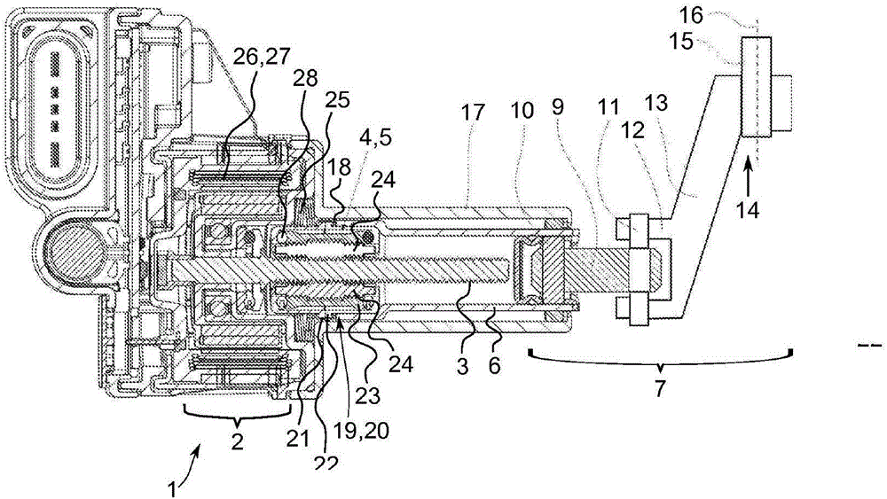
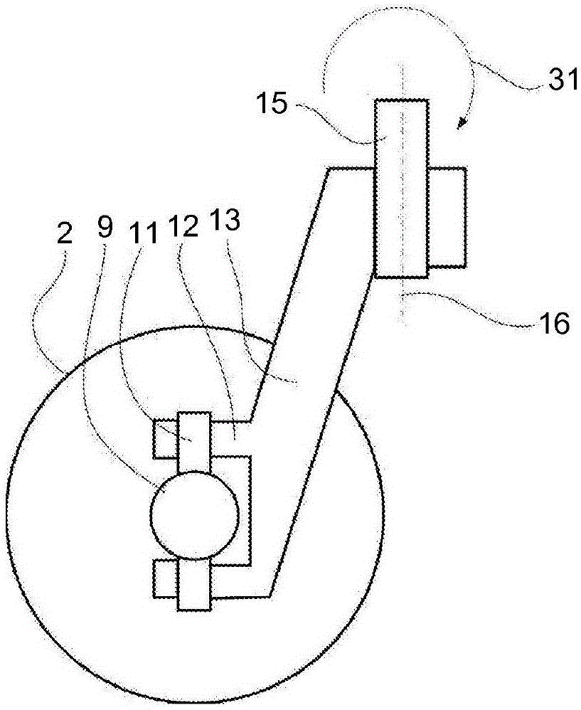
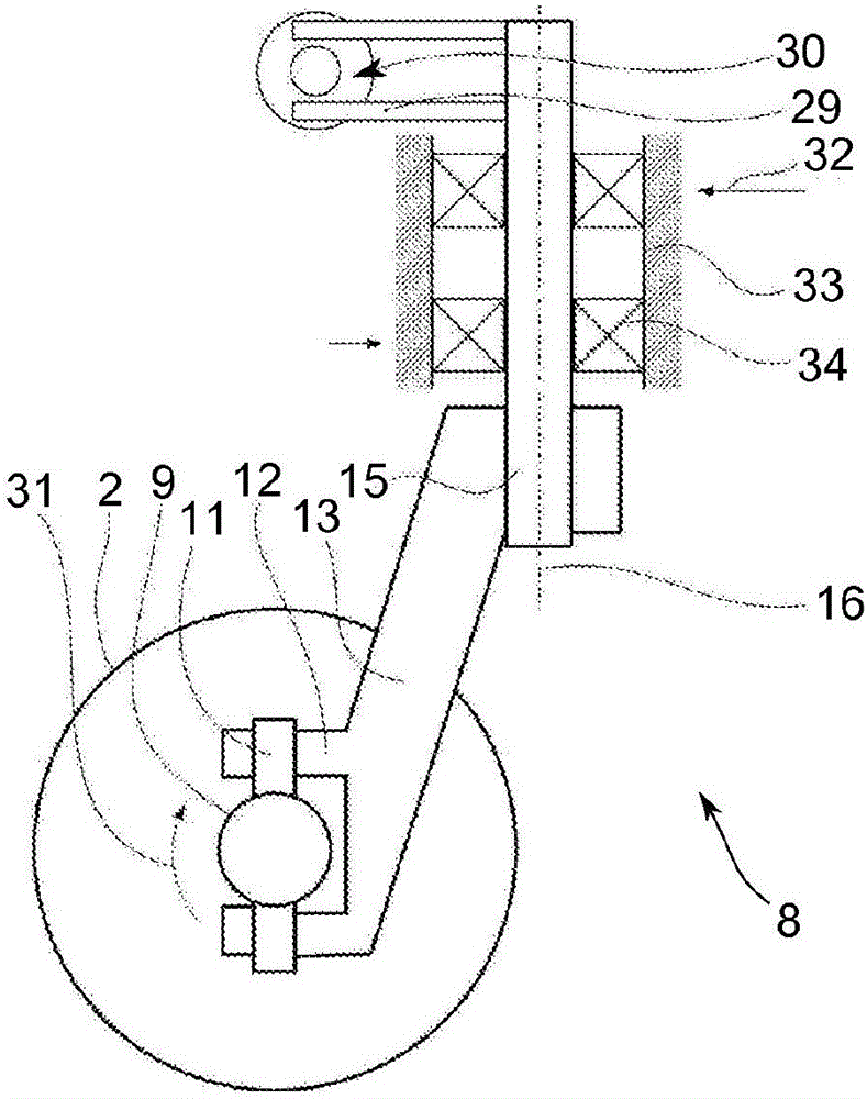
[0034] exist figure 1A first operating device 1 according to the invention is shown in . The actuating device 1 is dimensioned and provided for use in a clutch, such as a dual clutch, of a motor vehicle. The actuating device has an electromechanical actuator 2 . The actuator 2 contains a screw 3 which can be set in rotational motion by an electric motor. The screw 3 engages into a motion conversion transmission 4 . The motion conversion gear 4 is designed as a planetary roller gear (PWG) and has the reference numeral 5 . The planetary roller drive is connected / coupled to the pressure sleeve 6 in a pressure and / or tension transmission manner. The pressure sleeve 6 is coupled via a joint unit 7 to a clutch adjusting device 8 . The clutch adjustment device is especially clear in image 3 and 4 visible in .

[0035] back to figure 1 , it should be clarified that the planetary roller transmission (PWG) (5) is formed as a planetary roller transmission with accurate pitch. ...


PUM


Abstract

The invention relates to an actuating device for a motor vehicle, comprising an electromechanical actuator which has a spindle that can be set in a rotary movement by an electric motor, wherein said spindle can be coupled to a release device of a clutch via a motion conversion transmission that converts a rotational movement into a linear movement while transmitting pressure and/or traction to a pressure sleeve. The pressure sleeve thereby acts upon a clutch actuation device by means of a joint unit that secures the pressure sleeve against rotation. The invention also relates to a clutch having such an actuating device.

Description

technical field [0001] The invention relates to an actuation device for a motor vehicle having an electromechanical actuator with a screw which can be moved in rotation by an electric motor and which transmits pressure and / or tension to a pressure sleeve In the case of a motion transmission device that converts a rotary motion into a linear motion, it can be coupled to or coupled to a triggering device of a clutch, such as a clutch adjusting device. Background technique [0002] Clutch actuators are already known from the prior art, for example a hydrostatic clutch actuator is known from DE 10 2010 047 800 A1. A hydrostatic actuator is disclosed there, in particular a hydrostatic clutch actuator having a master cylinder which contains a housing and is axially displaceable in the housing A piston that pressurizes the pressure chamber; a transmission that converts the rotational drive into axial motion; and an electric motor with a stator and a rotor that drives the transmiss...

Claims


Application Information

Patent Timeline
IPC IPC(8): F16D23/12F16H25/22F16D28/00
CPCF16D23/12F16D28/00F16D2023/123F16H25/2252F16D2023/141
Inventor 拉尔斯·舒曼拉兹洛·曼彼得·格雷布
Owner SCHAEFFLER TECH AG & CO KG
Why Eureka
Try Eureka